PASCO EM-8656 AC_DC ELECTRONICS LABORATORY User Manual
Page 107
103
012-05892A
AC/DC Electronics Laboratory
®
➃
In the Physics Folder of the Science Workshop Experiment Library, open the document:
Macintosh: “P56 Transistor Lab 3” / Windows: “P56_TRN3.SWS”
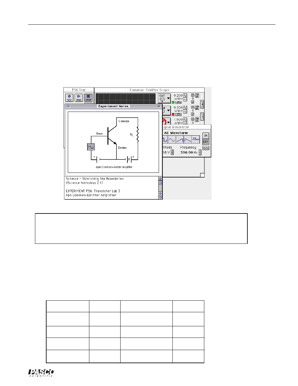
The document opens with a Scope display of Analog Output voltage (V) and Analog Channel A
voltage (V) versus Time (msec), and the Signal Generator window which controls the Power
Amplifier.
➤ NOTE: For quick reference, see the Experiment Notes window. To bring a display to the top,
click on its window or select the name of the display from the list at the end of the Display
menu. Change the Experiment Setup window by clicking on the “Zoom” box or the Restore
button in the upper right hand corner of that window.
➄
The Signal Generator is set to output Amplitude = ±0.20 V, AC Waveform = sine, at Frequency
= 300 Hz.
➅
Arrange the Scope display and the Signal Generator window so you can see both of them.
PART II: Sensor Calibration and Equipment Setup
•
You do not need to calibrate the Voltage Sensors or Power Amplifier. You will need the follow-
ing components:
Item
Quantity
Description
Quantity
1 k
Ω
resistor
4
10
µ
F capacitor
1
10 k
Ω
resistor
1
wire lead, five inch
4
22 k
Ω
resistor
2
wire lead, ten inch
1
1
µ
F capacitor
1
2N3904 transistor
1