PASCO EM-8656 AC_DC ELECTRONICS LABORATORY User Manual
Page 28
24
AC/DC Electronics Laboratory
012-05892A
®
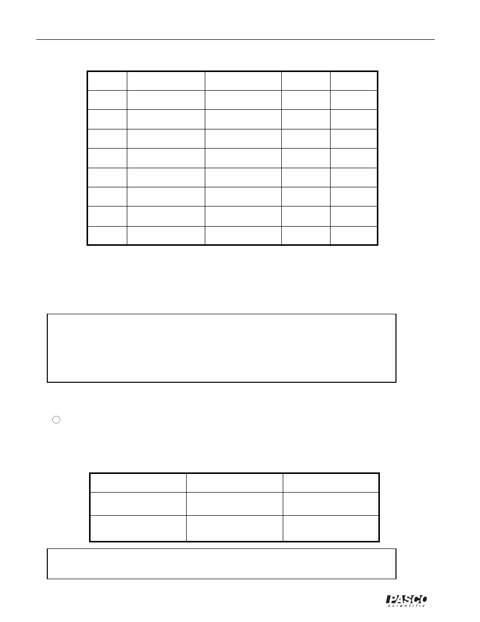
Table 8.1
Trial
Resistance
Capacitance
1
2
3
4
5
6
7
8
t
C
t
D
⑧
Replace the 100
µ
F capacitor with a 330
µ
F capacitor. Repeat step 7, recording the charging
and discharging times in Table 8.1. If a third value is available, include it in the data table, too.
⑨
Return to the original 100
µ
F capacitor, but put a 220 k
Ω
resistor in the circuit. Repeat step 7,
recording your data in Table 8.1. If a third resistor is provided, use it in the circuit, recording the
data.
➤ NOTE:
➀
What is the effect on charging and discharging times if the capacitance is increased? What
mathematical relationship exists between your times and the capacitance?
➁
What is the effect on charging and discharging times if the resistance of the circuit is
increased? What mathematical relationship exists between your times and the resistance?
➉
Return to the original 100 k
Ω
resistor, but use the 100
µ
F capacitor in series with the 330
µ
F
capacitor. Repeat step 7, recording your results in Table 8.2.
11
Now repeat step 7, but with the 100
µ
F and the 330
µ
F capacitors in parallel.
R = __________ C
1
= __________C
2
= __________
➤ NOTE: What is the effect on the total capacitance if capacitors are combined in series? What
if they are combined in parallel? (Refer to Table 8.2).
Type of Circuit
Series
Parallel
t
C
t
D
Table 8.2