PASCO EM-8656 AC_DC ELECTRONICS LABORATORY User Manual
Page 50
46
AC/DC Electronics Laboratory
012-05892A
®
➁
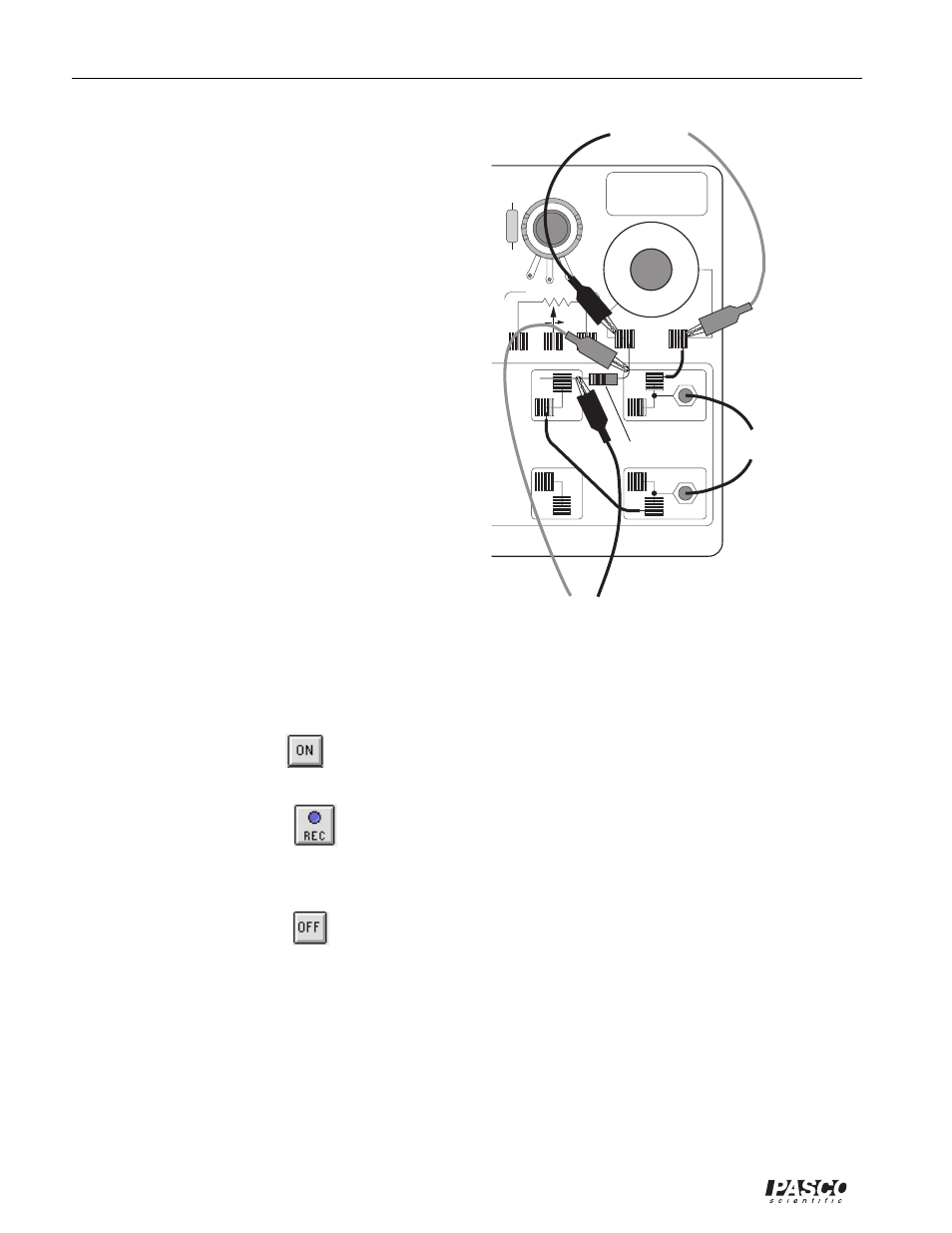
Connect the 10
Ω
resistor (brown, black, black)
between the component spring at the left hand edge
of the inductor coil, and the second component
spring to the left of the top banana jack.
➂
Connect another 5 inch wire lead between the
component spring nearest to the one in which one
end of the 10
Ω
resistor is connected, and a compo-
nent spring nearest to the bottom banana jack at the
lower right corner of the AC/DC Electronics Lab
Board.
➃
Put alligator clips on the banana plugs of both
Voltage Sensors. Connect the alligator clips of
Voltage Sensor “A” to the component springs at both
sides of the inductor coil.
➄
Connect the alligator clips of Voltage Sensor “B” to
the wires at both ends of the 10 resistor.
➅
Connect banana plug patch cords from the output of
the Power Amplifier to the banana jacks on the AC/
DC Electronics Lab Board.
Part III: Data Recording
➀
Use the multimeter to measure the resistance of the
inductor coil. Record the resistance in the Data Table.
➁
Use the multimeter to check the resistance of the 10
Ω
resistor. Record the resistance in the Data
Table.
➂
Turn on the power switch on the back of the Power Amplifier.
➃
Click the “ON” button (
) in the Signal Generator window. The power amplifier output will
begin.
➄
Click the “REC” button (
) to begin data recording.
•
Data recording will end automatically after 0.02 seconds. Run #1 will appear in the Data list in the
Experiment Setup window.
➅
Click the “OFF” button (
) in the Signal Generator window. Turn off the power switch on the
back of the Power Amplifier.
Analyzing the Data
•
The voltage across the resistor is in phase with the current. The voltage is also proportional to
the current (that is, V = IR). Therefore, the behavior of the current is studied indirectly by
studying the behavior of the voltage across the resistor (measured on Analog Channel B).
3 VOLTS MAX
C
W
.3
Ω
656
AC/DC ELECTRONICS LABORATORY
KIT NO.
to Power Amp.
to Channel B
to Channel A
10
Ω
Res