Exp 6- currents in circuits, Exp 7- kirchoff's rules – PASCO EM-8656 AC_DC ELECTRONICS LABORATORY User Manual
Page 122
118
AC/DC Electronics Laboratory
012-05892A
®
Exp 6- Currents in Circuits
➤NOTE:
The resistors used were:
R
1
=
100
Ω
R
2
=
330
Ω
R
3
=
560
Ω
These are the same resistors as were used in the
previous lab, and some of the data here originates in
lab 5.
Procedure
Series:
The current was the same—1.5 mA—no matter where it
was measured in the circuit.
Parallel:
Measurement Resistance
Current
Voltage
1
100
0.0156
1.574
2
330
0.0047
1.574
3
560
0.0028
1.574
123
67.5
0.0229
1.574
Discussion
In any resistance circuit—series, parallel, or both—the
voltage, current, and resistance are related by Ohm’s
Law:
V = IR
This pattern, and conclusion, should be apparent in
student data.
➤NOTE:
The product of the resistances and
currents obtained experimentally will generally be
lower than the measured voltage. This is due to the
nonzero resistance of the ammeter. When the meter
is in the circuit, its own resistance lessens the
current through that circuit. With most meters, this
error should be less than 5% or so.
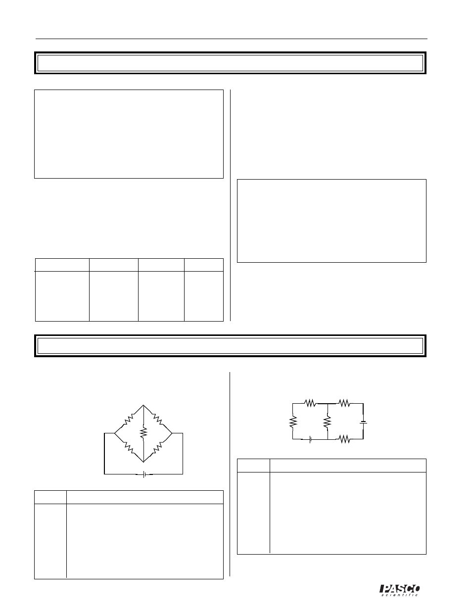
Exp 7- Kirchoff's Rules
The current leaving the node is equal to the current
entering the node. The sum of the voltage drops around a
closed loop equals zero.
Procedure
First circuit:
R (
Ω
)
V (V)
I (mA)
1
100
0.27
2.6
2
560
1.50
2.6
3
330
0.19
0.5
4
330
1.07
3.2
5
100
0.32
3.2
b1
1.573
2.6
b2
1.588
3.2
R (
Ω
)
V (V)
I (mA)
1
100
0.40
3.9
2
560
1.17
2.0
3
330
1.05
3.1
4
100
0.52
5.1
5
330
0.65
1.9
T
216
1.57
7.1
1
2
3
4
5
+
+
+
+
+
+
+
+
+
+
1
2
4
3
5
b1
b2
Second circuit: