Procedure: unit four – power supply – PASCO EM-8656 AC_DC ELECTRONICS LABORATORY User Manual
Page 82
78
AC/DC Electronics Laboratory
012-05892A
®
➆
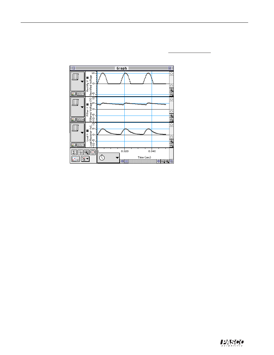
Type in “6.5” for the Max and -6.5 for the Min, and then click “OK”.
➇
Click anywhere on the vertical axis of the middle plot (Filtered Voltage). Type in “10” and “-10”
for the Max and Min and then click “OK. Repeat for the bottom plot (Load Resistor Voltage)
•
Optional: If a printer is available, select “Print Active Display” from the File menu.
PROCEDURE: Unit Four – Power Supply
PART I: Computer Setup
•
You do not need to change the computer setup.
PART II: Sensor Calibration and Equipment Setup
➀
Remove the 100
Ω
resistor from the AC/DC Electronics Lab Board.
➁
Put the diode between the second and third component springs to the left of the top banana jack.
Place the diode so the gray stripe (cathode) end is to the right (toward the banana jack).
➂
Place a second diode parallel to the first between the second and third component springs to the
left of the bottom banana jack. Place the diode so the gray stripe (cathode) end is to the right
(toward the banana jack).
➃
Place a third diode between the component spring at the right end of the top diode, and the
component spring at the right end of the bottom diode. Place the diode so the gray stripe (cathode)
is toward the bottom.
➄
Place a fourth diode between the component spring at the left end of the top diode, and the
component spring at the left end of the bottom diode. Place the diode so the gray stripe (cathode)
is toward the bottom.
•
The diode arrangement forms a square.