Procedure, Part i: computer setup – PASCO EM-8656 AC_DC ELECTRONICS LABORATORY User Manual
Page 106
102
AC/DC Electronics Laboratory
012-05892A
®
black
red
Power Amplifier
To Channel A
red
black
1 k
Ω
1
µ
F
22 k
Ω
10 k
Ω
2 k
Ω
1 k
Ω
IN
OUT
10
µ
F
22 k
Ω
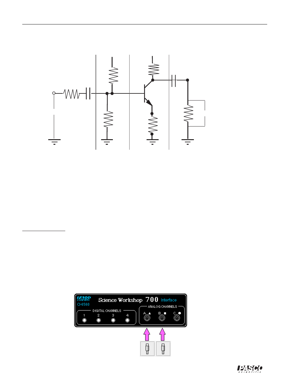
Section 1
Section 2
Section 3
Section 4
Input coupling
circuit
Bias
circuit
Amplifier
circuit
Output coupling
circuit
+5 V
+5 V
Each section of the common-emitter amplifier circuit performs a specific function. In Section 1,
the Input Coupling Circuit keeps DC voltages from changing the bias circuit. The function of
Section 2, the Bias Circuit, is to provide a voltage that keeps the transistor in its active region.
Section 3 is the Amplifier circuit. Section 4, the Output Coupling Circuit, allows only the AC
signal from the transistor to reach the load resistor so that the load resistance doesn’t affect the
operating voltage.
PROCEDURE
PART I: Computer Setup
➀
Connect the Science Workshop interface to the computer, turn on the interface, and turn on the
computer.
➁
Connect the Voltage Sensor to Analog Channel A.
➂
Connect the Power Amplifier to Analog Channel B. Plug the power cord into the back of the
Power Amplifier and connect the power cord to an appropriate electrical receptacle.