PASCO EM-8656 AC_DC ELECTRONICS LABORATORY User Manual
Page 35
31
012-05892A
AC/DC Electronics Laboratory
®
➄
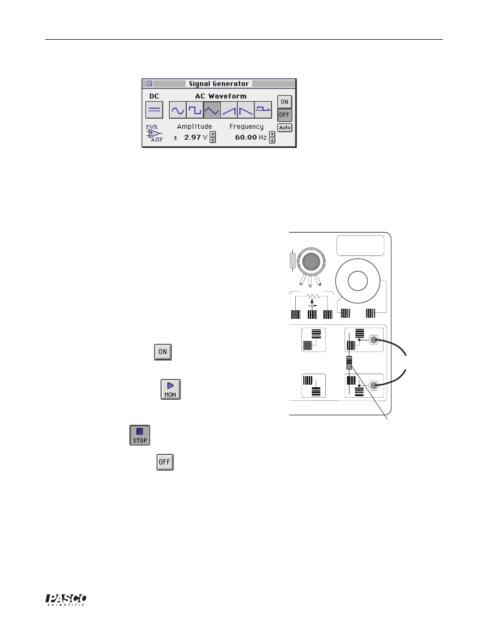
The Signal Generator is set to output 3.00 V, triangle AC waveform, at 60.00 Hz.
➅
The Scope is set to show Output Voltage on the vertical axis at 1.000 v/div and Current (Analog
A) on the horizontal axis at 0.100 v/div.
➆
Arrange the Scope display and the Signal Generator window so you can see both of them.
PART II: Sensor Calibration and Equipment Setup
•
You do not need to calibrate the Power Amplifier.
➀
Place a ten ohm (
Ω
) resistor in the pair of component springs
nearest to the banana jacks at the lower right corner of the
AC/DC Electronics Lab Board.
➁
Connect banana plug patch cords from the output of the
Power Amplifier to the banana jacks on the AC/DC Electron-
ics Lab Board.
➂
Turn on the power switch on the back of the Power Amplifier.
Part III: Data Recording – Resistor (10
Ω
)
➀
Click the “ON” button (
) in the Signal Generator
window.
➁
Click the “MON” button (
) in the Experiment Setup
window to start monitoring data. Observe the Scope display
of Voltage and Current. Wait a few seconds, then click the
“STOP” button (
).
➂
Click the “OFF” button (
) in the Signal Generator window. Turn off the power switch on
the back of the Power Amplifier.
3 VOLTS MAX
C
W
AC/DC ELECTRONICS LABORATORY
KIT NO.
to Power Amp.
10
Ω
(brown, black, black)