Induction – magnet through a coil, Experiment 20, Procedure – PASCO EM-8656 AC_DC ELECTRONICS LABORATORY User Manual
Page 113
109
012-05892A
AC/DC Electronics Laboratory
®
Experiment 20:
Induction – Magnet Through a Coil
EQUIPMENT NEEDED:
– Computer and Science Workshop™ Interface
– Voltage Sensor (CI-6503)
– AC/DC Electronics Lab Board (EM-8656)
– Alnico bar magnet (EM-8620)
– OPTIONAL: Photogate (ME-9204A or ME-9498)
Purpose
This experiment shows the Electromotive Force (EMF) induced in a coil by a magnet dropping
through the center of a coil.
Theory
When a magnet is passed through a coil there is a changing magnetic flux through the coil which
induces an Electromotive Force (EMF) in the coil. According to Faraday’s Law of Induction:
ε
= −
N
∆
φ
∆
t
where
ε
is the induced EMF, N is the number of turns of wire in the coil, and
∆ φ
∆
t
is the rate of
change of the flux through the coil.
In this experiment, a plot of the EMF vs. time is made and the area under the curve is found by
integration. This area represents the flux since
ε
∆
t
= −
N
∆
φ
PROCEDURE
PART I: Computer Setup
➀
Connect the Science Workshop interface to the computer, turn on the interface, and turn on the
computer.
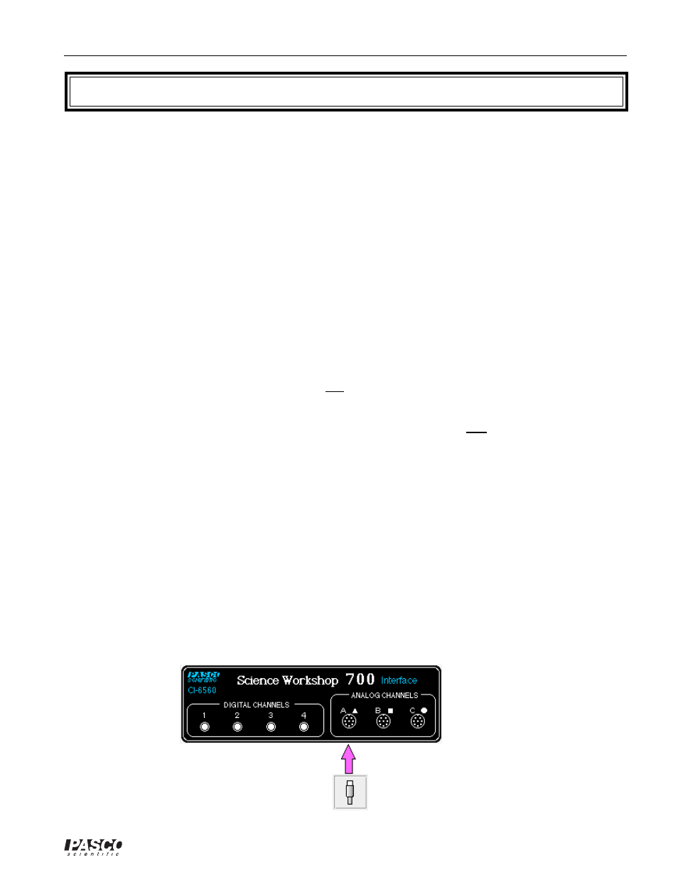
➁
Plug the DIN plug of the Voltage Sensor into Analog Channel A.