Getting started – PASCO EM-8656 AC_DC ELECTRONICS LABORATORY User Manual
Page 6
2
AC/DC Electronics Laboratory
012-05892A
®
EM-8656
AC/DC ELECTRONICS LABORATORY
3 VOLTS MAX
C
W
3.3
Ω
3 VOLT BULBS
A
B
C
C
B
E
KIT NO.
–
+
–
+
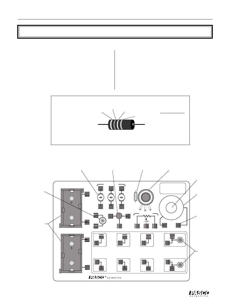
Getting Started
Battery Holder
Coil
Potentiometer
3.3
Ω
Resistor
Transistor socket
(3) Light Bulbs
and Sockets
Pushbutton
switch
Component
spring
Banana
Jacks
Board Layout
➀
Store the components in the Ziplock bag until needed.
Keep track of, and return the components to the
Ziplock bag after the experiment is completed.
➁
Identify the resistor value required for the individual
experiments with the help of the following chart.
➂
Familiarize yourself with the board layout, as shown.
➃
Students will need to use the same component layout
from one experiment to another. Labeling of the
boards and your meters will enable students to more
easily have continuity in their work. Using removable
labels or using a permanent marker are two alterna-
tives for marking the board.
1st Digit
2nd Digit
No. of Zeros
Tolerance
0
1
2
3
4
5
6
7
8
9
Black
Brown
Red
Orange
Yellow
Green
Blue
Violet
Gray
White
None
Silver
Gold
Red
±
20%
±
10%
±
5%
±
2%
Fourth Band
Resistor Chart
(for
Iron core)
- UI-5000 850 Universal Interface Quick Start (1 page)
- UI-5000 850 Universal Interface Instruction Manual (24 pages)
- PS-2193 High Current Sensor (2 pages)
- ME-8979 Mass and Hanger Set (1 page)
- ME-9498A Photogate Head (3 pages)
- ME-6821A Photogate Mounting Bracket (2 pages)
- ME-6825A MINI LAUNCHER (39 pages)
- ME-6810 Time of Flight Accessory (24 pages)
- ME-8574 DISCOVER FRICTION ACCESSORY (4 pages)
- PS-2103A Motion Sensor (4 pages)
- PS-2189 High Resolution Force Sensor (2 pages)
- ME-9448B Super Pulley with Clamp (2 pages)
- ME-6955 1.2 m PAScar Dynamics System (27 pages)
- PS-2104 Force Sensor (2 pages)
- ME-8998 Elastic Bumper Kit (2 pages)
- ME-6843 Spring Cart Launcher (9 pages)
- ME-6950 PAScar with Mass (29 pages)
- PS-2120A Rotary Motion Sensor (9 pages)
- PS-2120A Rotary Motion Sensor (17 pages)
- ME-9821 Centripetal Force Pendulum (18 pages)
- ME-8088 Centripetal Force Apparatus (20 pages)
- ME-8735 Large Rod Stand (2 pages)
- CI-6545 Force Accessory Bracket (3 pages)
- ME-9806 Photogate Brackets (1 page)
- CI-6692 IDS MOUNT ACCESSORY (2 pages)
- ME-6569 RMS_IDS KIT (36 pages)
- ME-6829 Mini Launcher Ballistic Pendulum (18 pages)
- ME-9889 Discover Free Fall System (10 pages)
- SE-7256 Motion Sensor Guard (2 pages)
- ME-8973 Discover Collision Bracket (2 pages)
- AP-8214A Stress_Strain Apparatus (12 pages)
- CI-6691 MINI-ROTATIONAL ACCESSORY (2 pages)
- ME-9833 Physical Pendulum Set (30 pages)
- OS-8473 POLARIZER SET (2 pages)
- PS-2343 USB Camera (2 pages)
- AP-8215A Gravitational Torsion Balance (20 pages)
- OS-8526A X-Y ADJUSTABLE DIODE LASER (2 pages)
- Xplorer-GLX Users’ Guide (152 pages)
- PS-2150 Broad Spectrum Light Sensor (2 pages)
- PS-2164 Quad Pressure Sensor (3 pages)
- PS-2200 Load Cell, 100 N (3 pages)
- PS-2205 Dual Load Cell Amplifier (5 pages)
- PS-2107 Absolute Pressure Sensor (2 pages)
- PS-2102 pH Sensor (3 pages)
- PS-2119 Acceleration Sensor (2 pages)