Procedure – PASCO EM-8656 AC_DC ELECTRONICS LABORATORY User Manual
Page 48
44
AC/DC Electronics Laboratory
012-05892A
®
Since the voltage across an inductor is given by
V
L
=
L
dI
dt
, the voltage across the inductor
starts at its maximum and then decreases exponentially:
V
L
=
V
o
e
−
( t
τ
)
After a time t >> t, a steady-state current I
max
is established and the voltage across the resistor is
equal to the applied voltage, V
o
. The voltage across the inductor is zero. If, after the maximum
current is established, the voltage source is turned off, the current will then decrease exponentially
to zero while the voltage across the resistor does the same and the inductor again produces a back
emf which decreases exponentially to zero. In summary:
DC Voltage applied:
DC Voltage turned off:
I
=
I
max
1
−
e
−
( t
τ
)
(
)
I
=
I
max
e
−
( t
τ
)
V
R
=
V
o
1
−
e
−
( t
τ
)
(
)
V
R
=
V
o
e
−
( t
τ
)
V
L
=
V
o
e
−
( t
τ
)
V
L
= V
0
1–e
–
(
t
/
τ)
At any time, Kirchhoff’s Loop Rule applies: The algebraic sum of all the voltages around the
series circuit is zero. In other words, the voltage across the resistor plus the voltage across the
inductor will add up to the source voltage.
Procedure
PART I: Computer Setup
➀
Connect the Science Workshop interface to the computer, turn on the interface, and turn on the
computer.
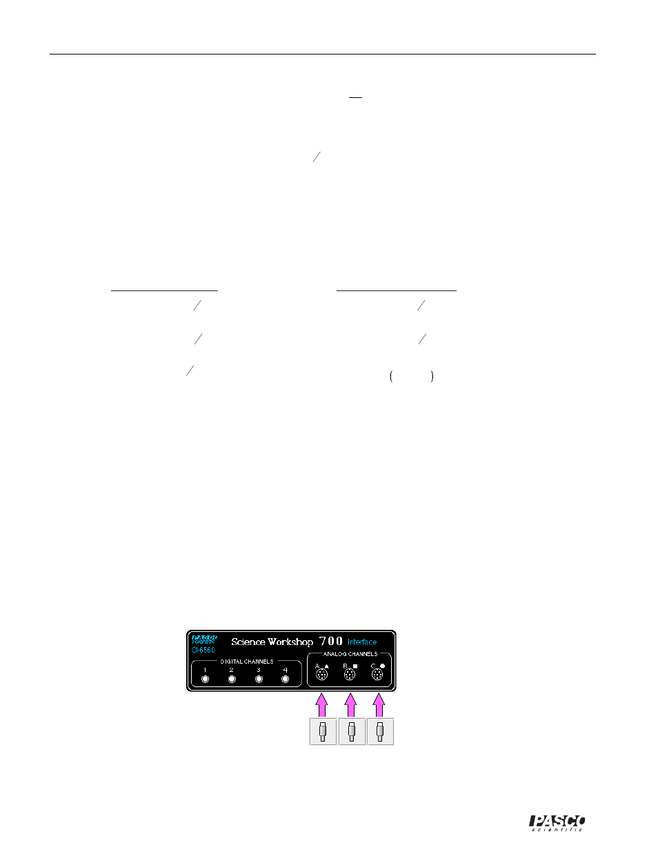
➁
Connect one Voltage Sensor to Analog Channel A. This sensor will be “Voltage Sensor A”.
Connect the second Voltage Sensor to Analog Channel B. This sensor will be “Voltage Sensor B”.
➂
Connect the Power Amplifier to Analog Channel C. Plug the power cord into the back of the
Power Amplifier and connect the power cord to an appropriate electrical receptacle
➃
In the Physics Folder of the Science Workshop Experiment Library, open the document:
Macintosh: “P50 LR Circuit” / Windows: “P50_LRCI.SWS”