Part ii: sensor calibration and equipment setup – PASCO EM-8656 AC_DC ELECTRONICS LABORATORY User Manual
Page 63
59
012-05892A
AC/DC Electronics Laboratory
®
➤ NOTE: For quick reference, see the Experiment Notes window. To bring a display to the top,
click on its window or select the name of the display from the list at the end of the Display
menu. Change the Experiment Setup window by clicking on the “Zoom” box or the Restore
button in the upper right hand corner of that window.
➄
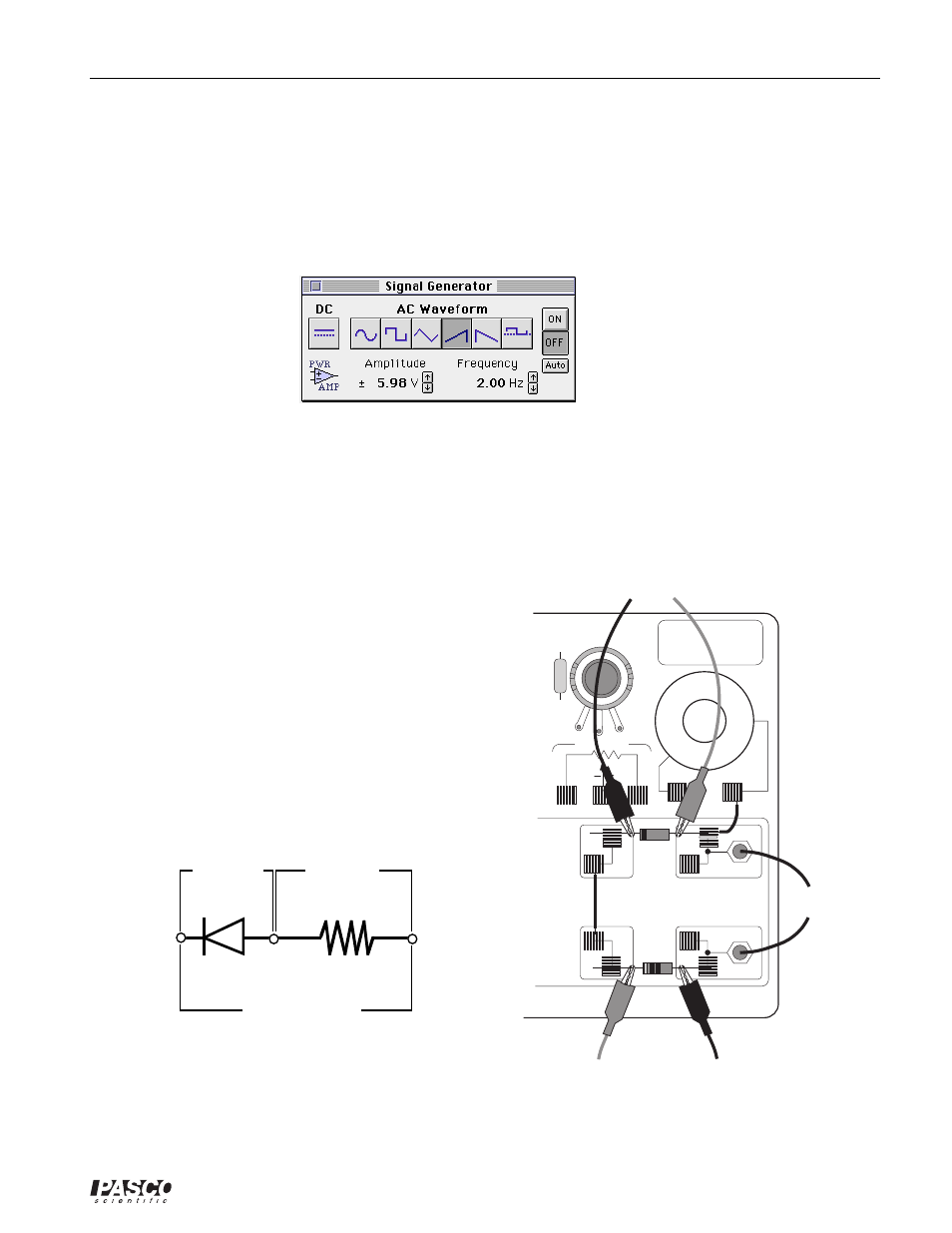
The Signal Generator is set to output 6.00 V, up-ramp AC waveform, at 2.00 Hz.
➅
The “Sampling Options…” are: Periodic Samples = Fast at 500 Hz, Start condition when Analog
Output = -5.9 V, and Stop condition when Samples = 250.
➆
Arrange the Graph display and the Signal Generator window so you can see both of them.
PART II: Sensor Calibration and Equipment Setup
•
You do not need to calibrate the Voltage Sensors or Power Amplifier.
➀
Connect the 1N-4007 diode (black with gray stripe
at one end) between the component spring next to
the top banana jack and the component spring to the
left of the banana jack. Arrange the diode so the
gray stripe is at the left end.
➁
Connect the 1 k
Ω
resistor (brown, black, red)
between the component spring next to the bottom
banana jack and the component spring to the left of
the bottom banana jack.
➂
Connect a 5 inch wire lead between the component
spring at the left end of the diode and the compo-
nent spring at the left end of the 1 k
Ω
resistor.
channel A
channel B
Power Amplifier
black
red
red
red
black
black
1000
Ω
Diode
➃
Put alligator clips on the banana plugs of both
voltage sensors. Connect the alligator clips of the
Channel A voltage sensor to the wires at both ends
of the diode.
EM-8656
AC/DC ELECTRONICS LABORATORY
3 VOLTS MAX
C
W
3.3
Ω
KIT NO.
to Power Amp
Diode
Res
to Channel B
to Channel A