Procedure – PASCO EM-8656 AC_DC ELECTRONICS LABORATORY User Manual
Page 90
86
AC/DC Electronics Laboratory
012-05892A
®
A transistor circuit can serve as a ‘digitial’ electric switch. In a mechanical electric switch, a small
amount of power is required to ‘switch on’ an electrical device (e.g., a motor) that can deliver a
large amount of power. In a ‘digital’ transistor circuit, a small amount of power supplied to the
base is used to “switch on” a much larger amount of power from the collector.
Here is some general information. A transistor is a three-terminal device. Voltage at a transistor
terminal relative to ground is indicated by a single subscript. For example, V
C
is the collector
voltage. Voltage between two terminals is indicated by a double subscript: V
BE
is the base-to-
emitter voltage drop, for instance. If the same letter is repeated, it means a power-supply voltage:
V
CC
is the positive power-supply voltage associated with the collector.
A typical npn transistor follows these “rules”:
➀
The collector must be more positive than the emitter.
➁
The base-to-emitter and base-to-collector circuits behave like diodes. The base-emitter diode is
normally conducting if the base is more positive than the emitter by 0.6 to 0.8 Volts (the
typical forward “turn on” voltage for a diode). The base-collector diode is reverse-biased. (See
previous experiments for information about diodes.)
➂
The transistor has maximum values of I
C
, I
B
, and V
CE
and other limits such as power dissipa-
tion (I
C
V
CE
) and temperature.
➃
If rules 1 – 3 are obeyed, the current gain (or amplification) is the ratio of the collector current,
I
C
, to the base current, I
B
. A small current flowing into the base controls a much larger current
flowing into the collector. The ratio, called “beta”, is typically around 100.
PROCEDURE
PART I: Computer Setup
➀
Connect the Science Workshop interface to the computer, turn on the interface, and turn on the
computer.
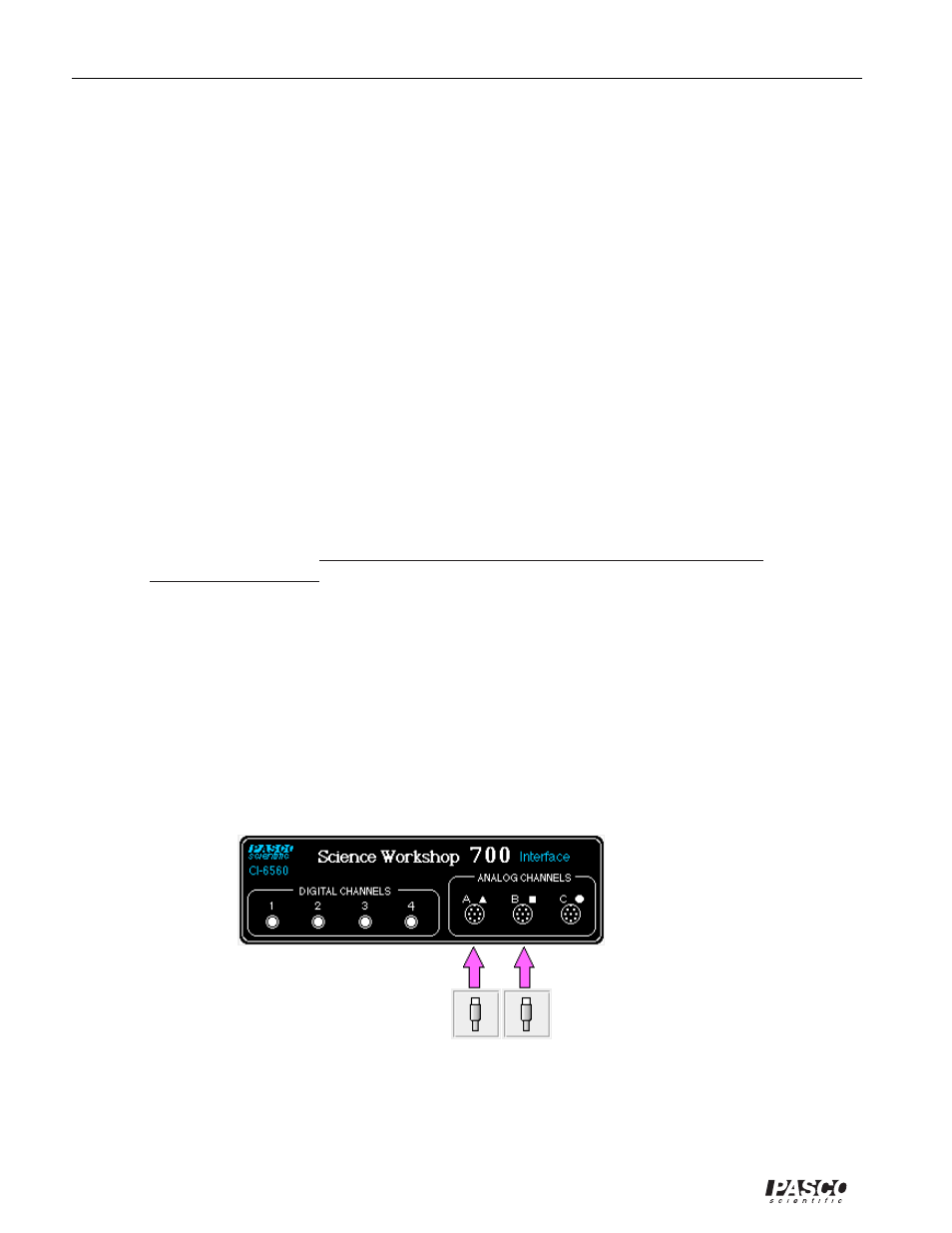
➁
Connect the Voltage Sensor to Analog Channel A.
➂
Connect the Power Amplifier to Analog Channel B. Plug the power cord into the back of the
Power Amplifier and connect the power cord to an appropriate electrical receptacle.
➃
In the Physics Folder of the Science Workshop Experiment Library, open the document:
Macintosh: “P54 Transistor Lab 1” / Windows: “P54_TRN1.SWS”