PASCO EM-8656 AC_DC ELECTRONICS LABORATORY User Manual
Page 97
93
012-05892A
AC/DC Electronics Laboratory
®
Experiment 18: Transistor Lab 2 – Current Gain:
The NPN Emitter-Follower Amplifier
EQUIPMENT NEEDED:
– Computer and Science Workshop™ Interface
– Power Amplifier (CI-6552A)
– (2) Voltage Sensor (CI-6503)
– AC/DC Electronics Lab Board (EM-8656)
– Regulated DC power supply of at least +5 Volts
– Banana plug patch cords (such as SE-9750)
Purpose
The purpose of this experiment is to investigate the direct current (DC) transfer characteristics of
the npn transistor, and to determine the current gain of the transistor.
Theory
Transistors are the basic elements in modern electronic amplifiers of all types. In a transistor
circuit, the current through the collector “loop” is controlled by the current to the base.
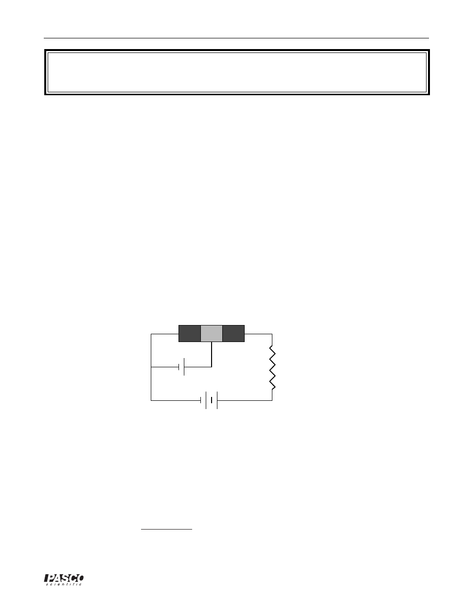
n
p
n
collector
base
emitter
Vsupply
n-p-n transistor
+
+
Vbase
Rload
The voltage applied to the base is called the base bias voltage. If it is positive, electrons in the
emitter are attracted onto the base. Since the base is very thin (approximately 1 micron), most of
the electrons in the emitter flow across into the collector, which is maintained at a positive
voltage. A relatively large current, I
C
, flows between collector and emitter and a much smaller
current, I
B
, flows through the base.
A small change in the base voltage due to an input signal causes a large change in the collector
current and therefore a large voltage drop across the output resistor, R
load
. The power dissipated
by the resistor may be much larger than the power supplied to the base by its voltage source. The
device functions as a power amplifier. What is important for amplification (or gain) is the
change in collector current for a given change in base current. Gain can be defined as the ratio of
output current to input current.
A transistor circuit can amplify current or voltage.