Experiment 6: currents in circuits – PASCO EM-8656 AC_DC ELECTRONICS LABORATORY User Manual
Page 23
19
012-05892A
AC/DC Electronics Laboratory
®
EQUIPMENT NEEDED:
– AC/DC Electronics Lab Board: Resistors and Wire Leads
– D-cell Battery
– Digital Multimeter
Purpose
The purpose of this lab will be to continue experimenting with the variables that contribute to the
operation of electrical circuits.
Procedure
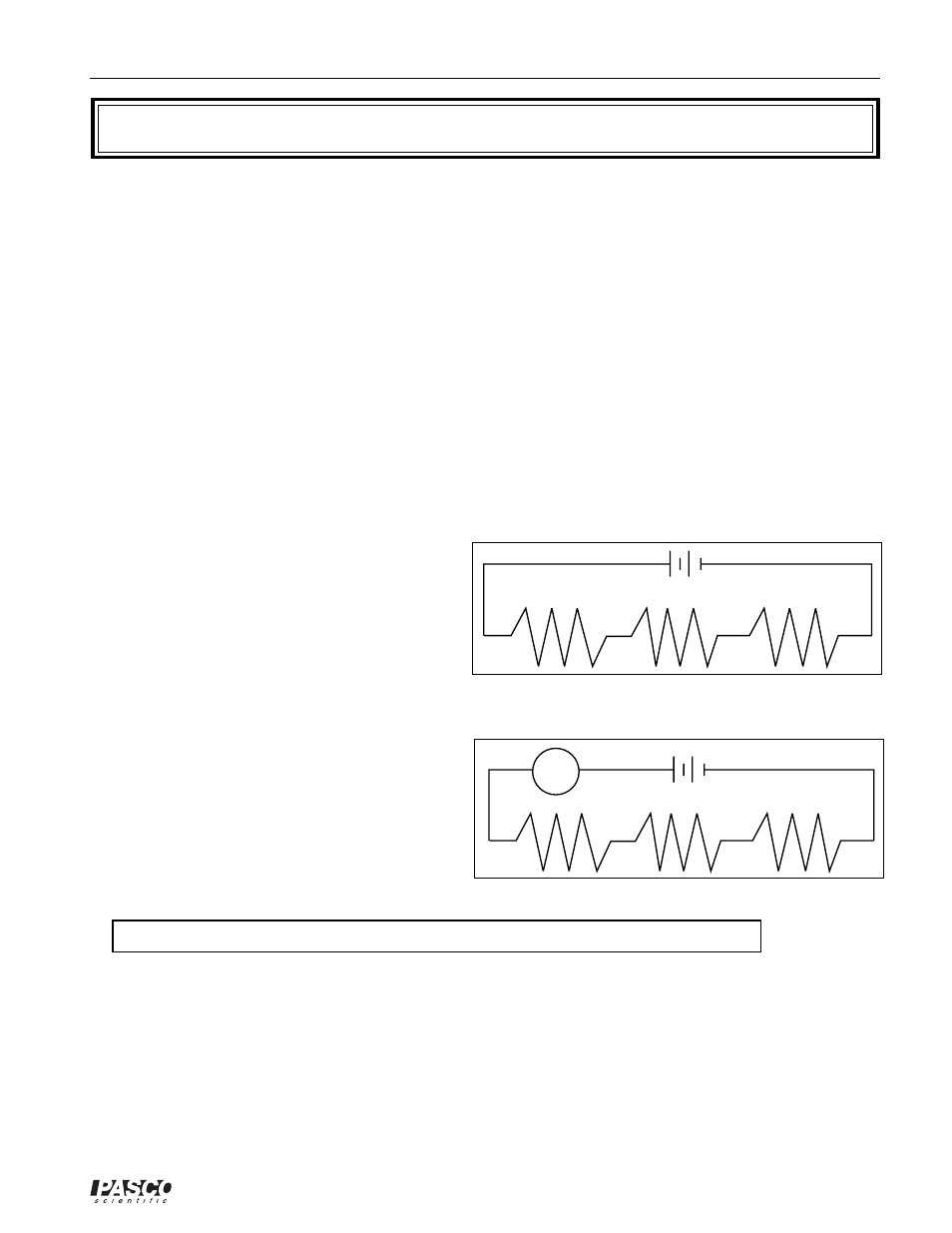
➀
Connect the same three resistors that you used in Experiments 3 and 4 into the series circuit shown
below, using the springs to hold the leads of the resistors together without bending them. Connect
two wires to the D-cell, and carefully note which lead is negative and which is positive.
Series
➁
Now change the leads in your DMM so that
they can be used to measure current. You
should be using the scale which goes to a
maximum of 200 mA. Be careful to observe
the polarity of the leads (red is +, black is -). In
order to measure current, the circuit must be
interrupted, and the current allowed to flow
through the meter. Disconnect the lead wire
from the positive terminal of the battery and
connect it to the red (+) lead of the meter.
Connect the black (-) lead to R
1
, where the wire
originally was connected. Record your reading
in the table as I
o
. See Figure 6.2.
➂
Now move the DMM to the positions indicated
in Figure 6.3, each time interrupting the circuit,
and carefully measuring the current in each one.
Complete the table on the top of the back page.
➤ NOTE: You will be carrying values from Experiments 3 and 4 into the table on the back.
Experiment 6: Currents in Circuits
Figure 6.1
+
-
- +
-
-
R
1
R
2
R
3
+
+
Figure 6.2
- +
-
R
1
+
-
+
R
3
R
2
I
0
+
-
+
-