PASCO EM-8656 AC_DC ELECTRONICS LABORATORY User Manual
Page 114
110
AC/DC Electronics Laboratory
012-05892A
®
➂
In the Physics Folder of the Science Workshop Experiment Library, open the document:
Macintosh: “P47 Induction-Magnet” / Windows: “P47_INDU.SWS”
The document opens with a Graph display of Voltage (V) versus Time (sec).
➤ NOTE: For quick reference, see the Experiment Notes window. To bring a display to the top,
click on its window or select the name of the display from the list at the end of the Display
menu. Change the Experiment Setup window by clicking on the “Zoom” box or the Restore
button in the upper right hand corner of that window.
➃
The “Sampling Options…” for this experiment are: Periodic Samples = Fast at 1000 Hz, Start
condition is voltage from Channel A = 0.08 V, Stop condition is Time = 0.5 seconds.
PART II: Sensor Calibration and Equipment Setup
•
You do not need to calibrate the Voltage Sensor.
➀
Put alligator clips on the ends of the voltage
sensor leads.
➁
Attach a clip to one component spring next to
the coil on the AC/DC Electronics Lab Board.
Attach the other clip to the other component
spring next to the coil.
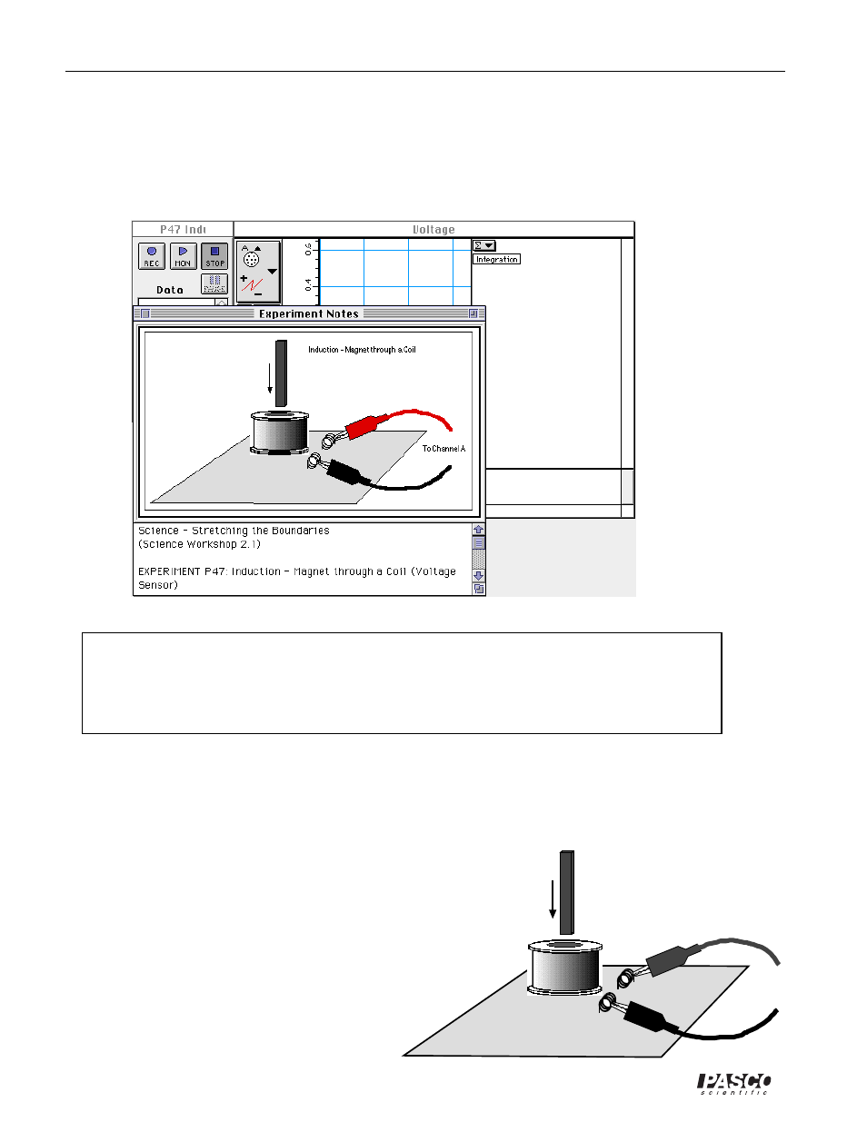
➂
Arrange the lab board so the corner with the coil
is beyond the edge of the table, and a magnet
dropped through the coil can fall freely.
To Channel A
Induction - Magnet through a Coil