PASCO EM-8656 AC_DC ELECTRONICS LABORATORY User Manual
Page 56
52
AC/DC Electronics Laboratory
012-05892A
®
Part III: Data Recording
➀
Turn on the power switch on the back of the power amplifier.
➁
Click the “MON” button (
) to begin data monitoring. Record the value of the frequency in
the Data Table.
•
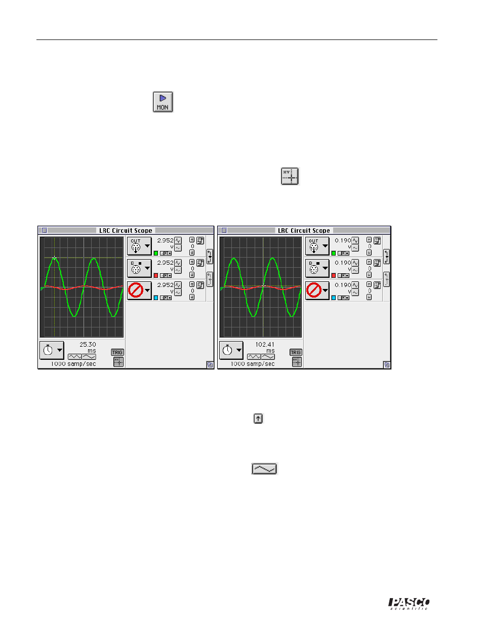
Use the Smart Cursor in the Scope to measure the source voltage and the resistor voltage. To find
the resonant frequency of the LRC circuit, adjust the frequency in the Signal Generator window
until the voltage across the resistor increases to a maximum value.
➂
To measure the output voltage, click the “Smart Cursor” button (
) in the Scope display. The
cursor changes to a cross-hair. Move the cursor/cross-hair to a peak of the output voltage, V
o
(trace for Channel A). Record the voltage that is displayed next the Input menu button.
➃
To measure the voltage across the resistor, move the cursor/cross-hair to a peak of the voltage
across the resistor, V
R
(trace for Channel B). Record the voltage.
➄
In the Signal Generator window, click on the Up arrow (
) to increase the frequency by 10 Hz.
Record the new frequency in the Data Table. Repeat the process of using the Smart Cursor to find
the new voltages for the output, V
o
, and the resistor, V
R
.
➅
Repeat the process until 150 Hz is reached. As the frequency is increased, adjust the sweep speed
in the Scope display using the “Increase Speed” button (
) as needed.
➆
Look at the Data Table and determine approximately the resonant frequency (where voltage
across the resistor reaches a maximum).
➇
Click on the frequency in the Signal Generator window to highlight it. Type in the approximate
resonant frequency, then press “enter”.