Micromod MOD: 30ML and Modcell Maintenance for 2001N, 2002N, and 1800R User Manual
Page 53
MOD30ML and Modcell Maintenance Manual
COMMUNICATIONS
ICN connector is labeled with a ground symbol; disregard this marking because the
terminal functions as the common connection.
6. Apply power to the equipment. If the network contains a Mini Link, allow at least 30
seconds for the link to initialize.
7. Verify that the ICN has proper termination. The most common termination method uses
the 2030F ICN terminator connected to the terminal block of one instrument on the
network.
•
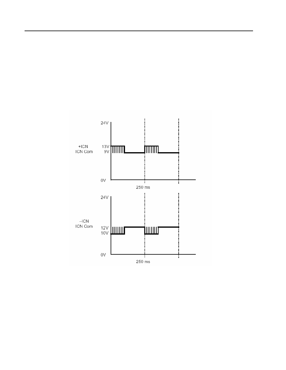
NOTE: Successful communication with any instrument on the network indicates
that the ICN is properly terminated and functioning correctly. Another method of
verifying proper ICN operation is to check the voltage pattern with an
oscilloscope. Typical voltage traces for a properly functioning ICN are shown in
the next figure.
Figure 4 .1. Voltage traces for a correctly functioning ICN
8. Start the Application Builder software and access the Serial Port Setup menu, Figure 3.2.
(see Section 3.2.1 for procedure). Select the serial port that is connected to the link and
confirm that the port settings match the link configuration. If uncertain of the link
configuration, select the default configuration parameters from Table 3.2.
9. Access the Communications Setup menu, Figure 3.5, (See Section 3.2.2 for procedure).
Set the Communication Type to Link Set the ICN number and Instrument address to
match the values determined in Step 3 or 4.
4 -4