Installation, 1 general mounting hints, Sp4000 – Liquid Controls SP4000 User Manual
Page 13: 2 mounting diagrams
SP4000 Flow Computer
10
2. Installation
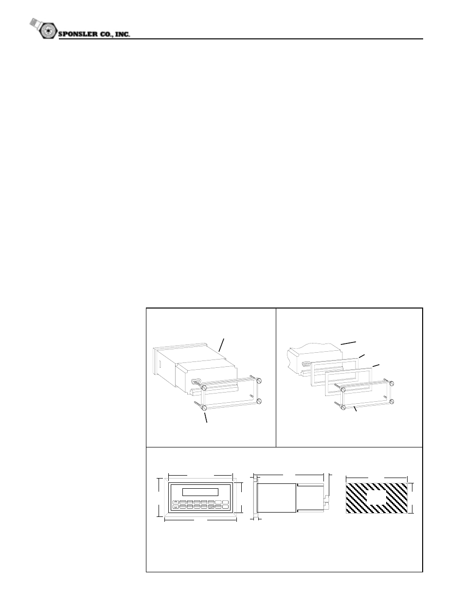
2.1 General Mounting Hints:
The SP4000 Flow Computer should be located in an area with a clean, dry
atmosphere which is relatively free of shock and vibration. The unit is installed in a
5.43" (138mm) wide by 2.68" (68mm) high panel cutout. (see Mounting Dimensions)
To mount the Flow Computer, proceed as follows:
a. Prepare the panel opening.
b. Slide the unit through the panel cutout until the it touches the panel.
c. Install the screws (provided) in the mounting bracket and slip the bracket over the
rear of the case until it snaps in place.
d. Tighten the screws firmly to attach the bezel to the panel. 3 in. lb. of torque must
be applied and the bezel must be parallel to the panel.
NOTE: To seal to NEMA4X / IP65 specifications, supplied bezel kit must be used
and panel cannot flex more than .010".
When the optional bezel kit is used, the bezel adaptor must be sealed to the
case using an RTV type sealer to maintain NEMA4X / IP65 rating.
General Mounting Hints
Mounting Procedure
NEMA4X / IP65 Specifications
SP4000
SP4000
Bezel Adaptor
Gasket
Mounting Bracket
Mounting Bracket
Standard Mounting
Bezel Kit Mounting
Dimensions
Dotted Line Shows Optional Bezel Kit
Panel
Cutout
5.43
(138)
2.68
(68)
Dimensions are in inches (mm)
5.67 (144)
2.83
(72)
3.43
(87)
6.18
STOP
START
5
0
–
TIME
CLEAR
•
MENU
ENTER
HELP
TEMP
4
PRE 1
3
RATE
2
TOTAL
1
GRAND
6
SCROLL
7
PRE 2
8
DENS
9
RATE
TOTAL 267395.749
GPM
GAL
147.43
6.15
(156)
0.5
(13)
0.28 (7.2)
0.4 (10)
2.2 Mounting Diagrams: