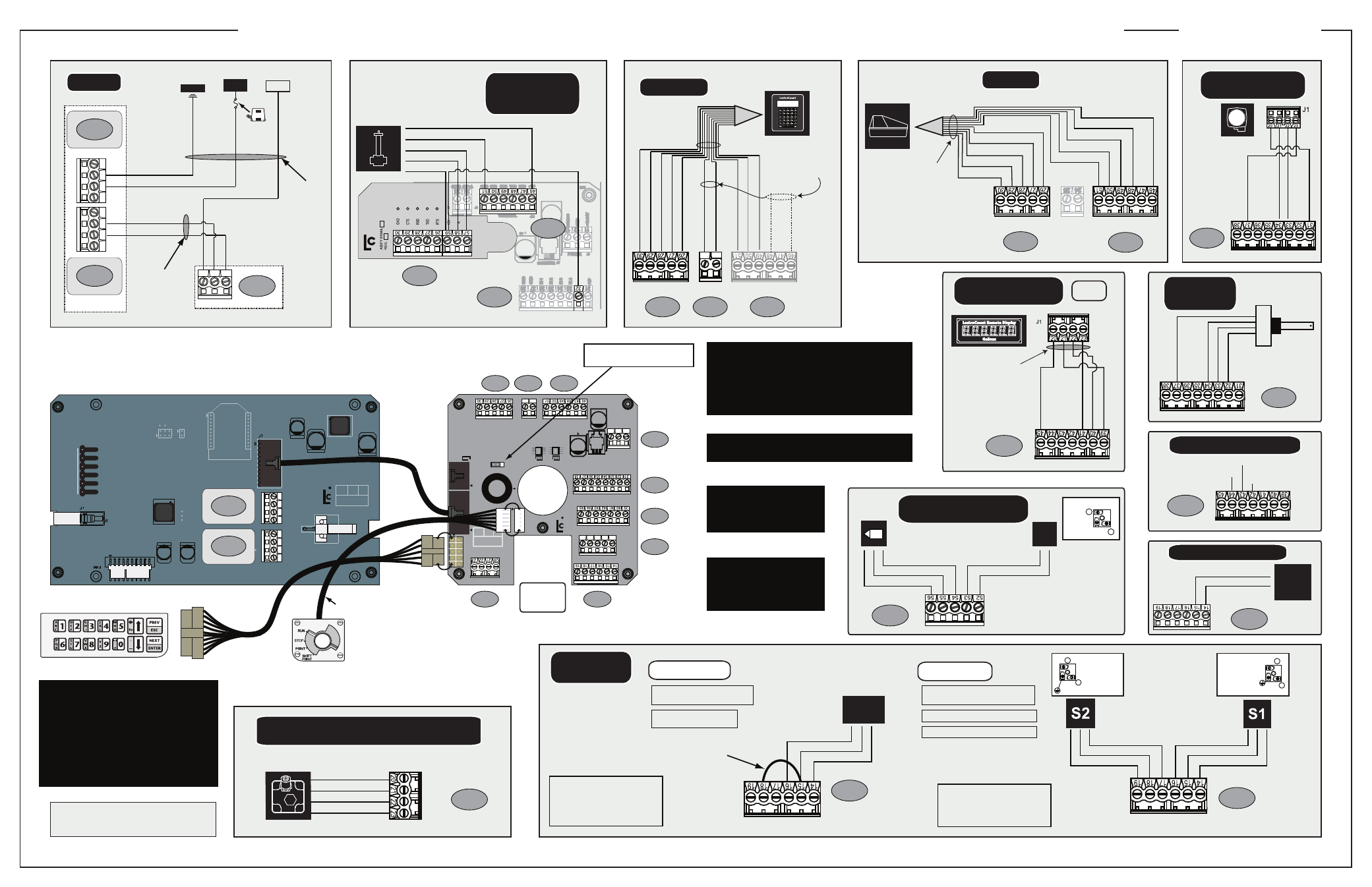
Liquid Controls LCR600 Wiring Schematic User Manual
S1&2, Two stage, Single stage
84042 Keypad
J6
84063
Keypad Cable
81832
LCR 600
Switch Harness
84048
LCR 600 Switch Plate
84057
Display
Board Cable
52
5354
55
56
PRINTER
SERIAL 485
TERMINAL
POWER
COUNTER
MH1
CTS RXD TXD RTS
GND
GND
485+A
485-B
CTS RXD TXD RTS +VP
EARTH
AUX OUTPUTS
PULSE INPUTS
AUX I/O
GND
GND
GND
IN 1
OUT1
OUT2
OUT3
TEMPERATURE PROBE
ASSY
84040 REV.
RTD+S
RTD-D1
RTE-S
RTD+D
OUT4
OUT5
IN 2
IN 3
IN 4
+5V OUT
+VP
+VP
PGND
OUT6 +VP
SOL
+VP
PGNDOUT7
+VF
+VF
IN5
OUT8
GND
GND
+12-24V
MH4
C1
J20
J3
J2
J1
J7
J12
J15
P1
TP1
J5
J14
J18
J19
J10
J17
J11
J7
C2
MH5
MH3
MH2
A
B
24
25
11
12
13
11
10
12
13
11
10
12
13
MH3
P1
J4
RF1
C3+
C4+
L10
C5+
MH5
MH7
MH1
RS-232
GND
T-RTS
J10
T-TXD
T-CTS
T-RXD
+VP
MH4
J11
C1+
J10
L9
MH2
C2+
J8
J6
ASSY
84044
REV
J9
MH6
MH8
EARTH
ACC
GND
+12 - 24V
EARTH
ACC
GND
+12 - 24V
J8
Terminal
Display Board
J9
Terminal
Display Board
J1
Terminal
J2
Terminal
J3
Terminal
J6
Terminal
J8
Terminal
J12
Terminal
J15
Terminal
J13
Terminal
J14
Terminal
CPU
84040
84044 LCR 600 Display Interface Board
LECTROCOUNT LCR 600 CPU 840404 WIRING SCHEMATIC
E3700/E3701
825001
Printer Power Cable
PO
WER J8
PO
WER J9
11
10
12
13
11
10
12
13
J8
Terminal
Display Board
J9
Terminal
Display Board
84044
Display Board
PULSE OUTPUT
DEVICE (POD) 1-4
GND
/Blac
k
(37)
CHB/
Green
(34)
CHA/
White
(33)
+V
o/
Re
d (31)
J8
Terminal
DMS i1000
J1
Terminal
J2
Terminal
J3
Terminal
81513040
Black Data
Cable 40’
Violet and red
wires move from
48 & 46 to
25 & 24
+VP
/R
ed
(24)
TXD/
Violet
(25)
RXD/
Gr
ay
(49)
CTS/
Green
(50)
GND/
White
(51)
GND/
Blac
k
(30)
CTS/
Blue
(29)
RXD/
Yello
w
(28)
TXD/
Or
ang
e
(27)
RTS/
Br
own
(26)
24
25
SERIAL J2
TERMINAL J3
PRINTER J1
TEMPERA
TURE PROBE
White (20)
White (21)
Red (22)
Red (23)
J14
Terminal
ETVC
(Electronic Temperature Volume Compensation)
71130 Temperature Probe
J8
Terminal
11
12
13
PRINTER
SERIAL 485
TERMINAL
POWER
COUNTER
MH1
CTS RXD TXD RTS
GND
GND
485+A
485-B
CTS RXD TXD RTS +VP
EARTH
GND
GND
IN 1
IN 2
IN 3
IN 4
+5V OUT
+VP
GND
+12-24V
MH4
J20
J6
J3
J2
J1
J7
J7
C2
24
25
+5V(Out)/Jumper
(59 to 32)
A/Blue (58)
+5V/Red (59)
B/Yellow (57)
GND/White (51)
+VP/Black (46)
B
DIFFERENTIAL
PRESSURE (∆P)
TRANSDUCER
J1
Terminal
J3
Terminal
82637
∆P Transducer Kit
81944
DP/Printer
Board
Auxiliary Output 1 (Out 1)
Auxiliary Output 2 (Out 2)
Pulse Output (Out 3)
J12
Terminal
AUXILIARY OUTPUTS
SOLENOID
VALVES
J13
Terminal
Jumper from
Terminal 15
to Terminal 18
Earth/Green (16)
Out7/Black (15)
+12V/Black (14)
S1&2
J13
Terminal
Earth/Green (16)
Earth/Green (19)
Out7/Black (15)
Out6/Black (18)
+12V/Black (14)
+12V/Black (17)
Earth/Green (19)
Out6/Black (18)
+12V/Black (17)
2
1
Earth/Green (16)
Out7/Black (15)
+12V/Black (14)
2
1
Two Stage
81527 3-Way Solenoid (LPG)
A2859-11 Block Valve (LPG)
A2848-11 Two Stage Block Valve
A2982 E-7 Two Stage Piston Valve
Single Stage
81527 3-Way Solenoid (LPG)
A2843 Block Valve (LPG)
A2847-11
Single Stage Block Valve
Power, input and output (I/O) wiring must be in accordance
with the area classification for which it is used (Class I, Div 1).
For North America, installations must be per the U. S. National
Electrical Code, NFPA 70, or the Canadian Electrical Code
in order to maintain Class I, Division 1 ratings. This may
require using connections or other adaptations in accordance
with the requirements of the authority having jurisdiction.
WARNING: Explosion Hazard - Substitution of components
may impair suitability for Class I, Division 1 applications.
WARNING: Explosion Hazard -
When in hazardous locations,
turn power OFF before replacing
or wiring modules.
WARNING: Explosion Hazard -
Do NOT disconnect equipment
unless power has been switched
OFF or the area is known to be
Non-Hazardous.
For positive ground installation,
contact the Liquid Controls Service Department
J10 Communications Jumper
LCR 600 - Always in B position
Keep gray
wire at bottom
Solenoid operated valve 81527
(3-way LPG solenoid) has 3 cables
potted into the housing. All other
solenoid operated valves on Liquid
Controls valves use cable assembly
81859, which has 2 cables.
The Earth grounds for Terminals 16
& 19 are optional. The solenoid
operated valves are grounded
through the component they are
mounted on.
PRINTER
+VP/Red (46)
TXD/Violet (48)
RXD/Gray (49)
CTS/Green (50)
GND/White (51)
GND/Black (30)
CTS/Blue (29)
RXD/Yellow (28)
TXD/Orange (27)
RTS/Brown (26)
J1
Terminal
J3
Terminal
81513040
Black Data
Cable 40’
TERMINAL J3
PRINTER J1
24
25
GND/
Blac
k (37)
CHB/
Green
(34)
CHA/
White
(33)
+5/
Re
d (32)
INTERNAL
PULSER
J8
Terminal
82597
Internal Pulser Kit
(or POD 5)
84046
40' Gray
Power
Cable
84061
Internal
Power
Cable
EARTH/Shield (13)
GND/Black (12)
+12-24/Red (11)
7.5A
In-Line
Fuse
Open
Drain
Battery or
Accessory Panel
GROUND
DC
Power
Supply
Power
Supply
+12-24
GND
+12-24/Red
GND/Black
EAR
TH
POWER
11
12
13
POWER J6
J6
Terminal
84040 Board
J3 Terminal
can be
disconnected
GND/
Blac
k (41)
DN/
Green
(40)
+V
o/
Re
d (45)
UP/
White
(39)
LECTROCOUNT
REMOTE DISPLAY
J12
Terminal
81816
Remote Display Cable
E1640
ONLY
OPTICAL AIR AND
VAPOR ELIMINATORS
81947
Optical Sensor
502011
S3 Solenoid Valve
Gnd/Black (54)
In5/White (55)
+VP/Red (52)
Out8/Black (53)
+VP/Red (56)
Out8/Black (53)
+VP/Red (52)
2
1
S3
J15
Terminal
ESD PRECAUTION OPENING LECTROCOUNT REGISTERS
Before opening the LectroCount register and
handling the CPU board, it is important to discharge
any ESD that may have built up on your person. To
discharge ESD from your person, touch a
well-grounded point such as the LectroCount register
housing, the meter, the truck piping, or the bumper.
When the maintenance is complete and the LectroCount
register door is closed, the CPU board is protected from
ESD by the LectroCount register housing which is
grounded to the chassis.
SOL
J13
SOL
J13
AUXILIARY DEVICE
i.e Dead-Man
Shutdown
Auxiliary
Device
J13
Terminal
Out7
+Vo
SOL
J13
AUX I/O
J15
AUX OUTPUTS
J12
AUX OUTPUTS
J12
PULSE OUTPUTS
J8
PULSE OUTPUTS
J8