Diagnosis and troubleshooting, 2 diagnosis flow chart and troubleshooting – Liquid Controls SP4000 User Manual
Page 115
SP4000 Flow Computer
112
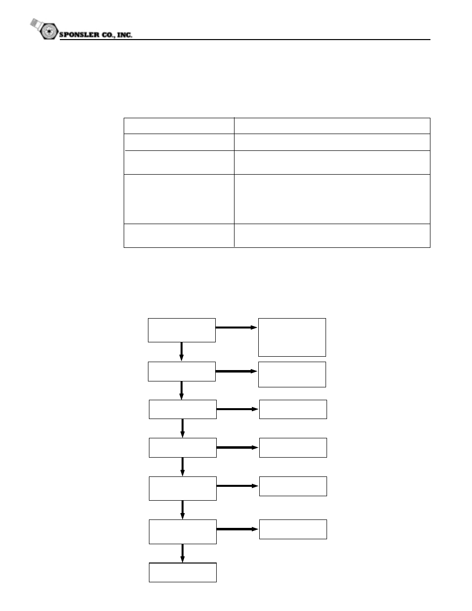
12.2 Diagnosis Flow Chart and Troubleshooting
All instruments undergo various stages of quality control during production. The last of these stages is
a complete calibration carried out on state-of-the-art calibration rigs.
A summary of possible causes is given below to help you identify faults.
Is there a power supply
voltage across Terminals
23 and 24?
No
Yes
Check the connections
according to the circuit
diagrams.
Check junction box fuses.
Is the Display Backligh
Visible?
No
Yes
Check/Replace internal
fuse. If fuse is OK,
Factory Service Required
Is there a black bar
across the display?
Yes
No
Factory Service Required
Does the display
alternate between blank
and sign on message?
Yes
No
Does the display show
an error message?
Yes
No
See section 12.3 for
cause and remedy.
No system or process
errors present.
Are the Display
Characters Visible?
No
Yes
Factory Service Required
Factory Service Required
12. Diagnosis and Troubleshooting
12.1 Response of SP4000 on Error or Alarm:
Error indications which occur during operation are indicated alternately with the measured values. The
SP4000 Flow Computer has four types of error:
TYPE OF ERROR
DESCRIPTION
System Alarms
Errors detected due to system failure
Sensor/Process Alarms
Errors detected due to sensor failure or
process alarm conditions
Service Test Errors
Errors detected due to problems found during
service test. (Service test can only be
performed by qualified Factory service
technicians because service code and special
equipment are needed)
Self Test Errors
Errors detected during self test. (Each time
the unit is powered, it runs a self test)