4 switch–on phase, 4 switch-on phase – Burkert Type 8136 User Manual
Page 28
5
1
2
+
( )
(-)
6
7
8
4...20mA
2
3
4
1
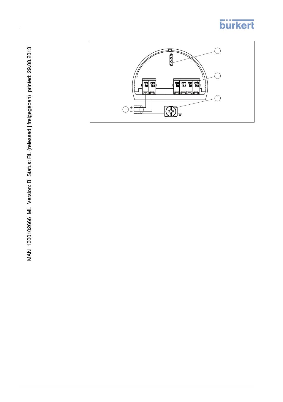
Fig. 23: Electronics and connection compartment, single chamber housing
1
Voltage supply, signal output
2
For indicating and adjustment module or interface adapter
3
For external indicating and adjustment unit
4
Ground terminal for connection of the cable screen
5
.4 Switch-on phase
After connecting the instrument to power supply or after a voltage
recurrence, the instrument carries out a self-check for approx. 30 s:
l
Internal check of the electronics
l
Indication of the instrument type, hardware and software version,
measurement loop name on the display or PC
l
Indication of the status message "F 105 Determine measured
value" on the display or PC
l
The output signal jumps to the set error current
As soon as a plausible measured value is found, the corresponding
current is outputted to the signal cable. The value corresponds to the
actual level as well as the settings already carried out, e.g. factory
setting.
Electronics compart-
ment
28
LEVEL TRANSMITTER 8136 • 4 … 20 mA/HART - two-wire
5 Connecting to power supply
41783
-EN
-120316