Burkert Type 8136 User Manual
Page 18
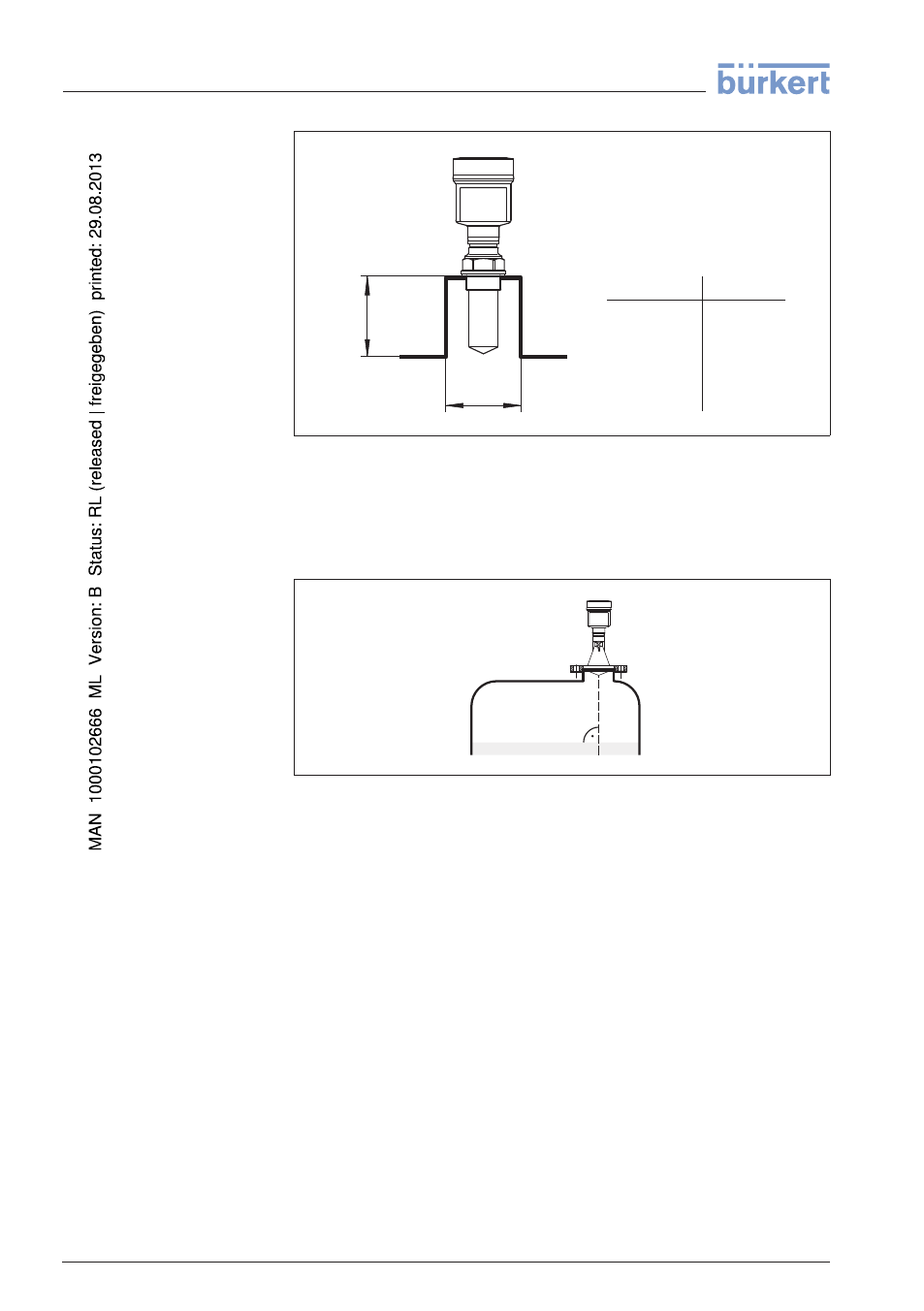
d
h
d
h
1½"
50 mm/2"
80 mm/3"
100 mm/4"
150 mm/6"
200 mm
250 mm
300 mm
500 mm
800 mm
Fig. 14: Deviating socket dimensions
Align the sensor in liquids as vertical as possible to the product surface
to achieve optimum measurement results.
Fig. 15: Alignment in liquids
The mounting location of the radar sensor should be a place where no
other equipment or fixtures cross the path of the microwave signals.
Vessel installations, such as e.g. ladders, limit switches, heating
spirals, struts, etc., can cause false echoes and impair the useful echo.
Make sure when planning your measuring site that the radar sensor
has a "clear view" to the measured product.
In case of existing vessel installations, a false echo storage should be
carried out during setup.
If large vessel installations such as struts or supports cause false
echoes, these can be attenuated through supplementary measures.
Small, inclined sheet metal baffles above the installations scatter the
radar signals and prevent direct interfering reflections.
Sensor orientation
Vessel installations
18
LEVEL TRANSMITTER 8136 • 4 … 20 mA/HART - two-wire
4 Mounting
41783
-EN
-120316