3 wiring plan – Burkert Type 8136 User Manual
Page 27
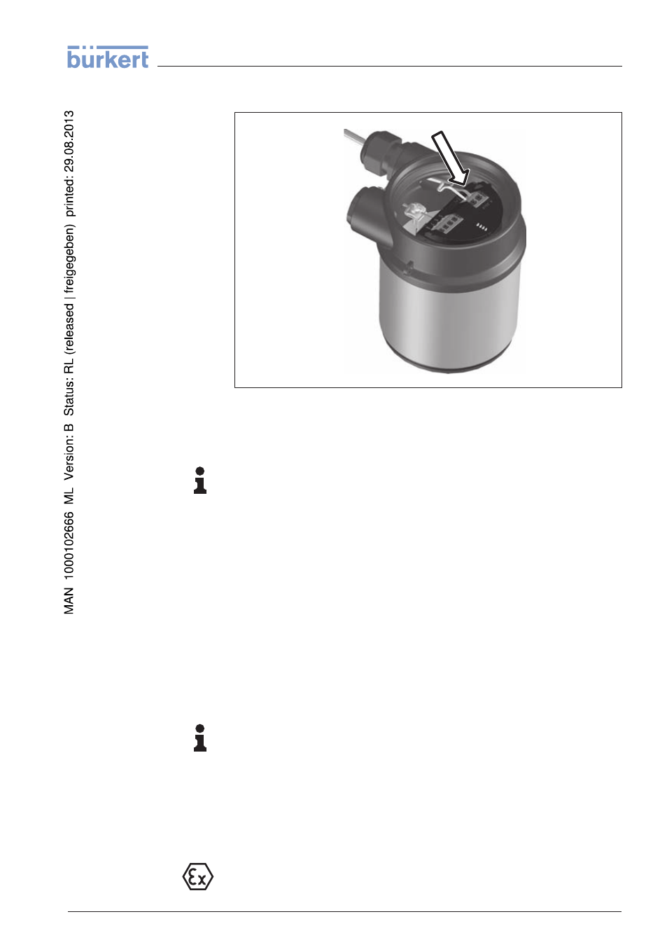
5
Insert the cable into the sensor through the cable entry
Fig. 22: Connection steps 5 and 6
6
Insert the wire ends into the terminals according to the wiring plan
Information:
Solid cores as well as flexible cores with cable end sleeves are
inserted directly into the terminal openings. In case of flexible cores
without end sleeves, press the terminal head with a small screwdriver;
the terminal opening is freed. When the screwdriver is released, the
terminal closes again.
7
Check the hold of the wires in the terminals by lightly pulling on
them
8
Connect the screen to the internal ground terminal, connect the
outer ground terminal to potential equalisation
9
Tighten the compression nut of the cable entry. The seal ring must
completely encircle the cable
10 Screw the housing cover back on
The electrical connection is finished.
Information:
The terminal block is pluggable and can be removed from the
electronics. To do this, lift the terminal block with a small screwdriver
and pull it out. When inserting the terminal block again, you should
hear it snap in.
5
.3 Wiring plan
The following illustration applies to the non-Ex as well as to the Ex-ia
version.
LEVEL TRANSMITTER 8136 • 4 … 20 mA/HART - two-wire
27
5 Connecting to power supply
41783
-EN
-
120316