Burkert Type 8035 User Manual
Page 51
49
Operatingandfunctions
9.3
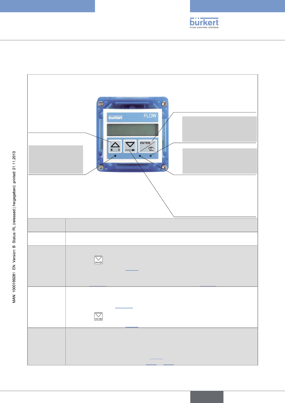
Description of the navigation keys and the state
leDs
• Selecting the displayed
parameter
• Confirming the settings
State LED of relay output DO3
(LED ON = contact closed)
• Reading the messages
• Scrolling through the parameters
• Selecting the figure on the left
• Scrolling up the
parameters
• Incrementing the figure
selected
• Consulting the history
of dosings
Device state LED: see
following table.
State LED of relay output DO2
(LED ON = contact closed)
Device state
leD
state of the device
Green
The device operates correctly.
Orange
An alarm related to the dosing and/or a warning message has been generated.
→
Press the
key for 2 seconds in the Process level to access the message if no dosing
is being done. See chap. “10.3” for the meaning of the message.
Furthermore, output DO1, DO3 or DO4 switches if configured with the function "ALARM"
(see chap. “9.7.19”
) or with the function "WARNING" (see chap. “9.7.20”)
Red
An error message has been generated.
The transistor output DO4 sends out a 10 Hz frequency, if parameter "ERR. 10HZ" is set to
"10HZ ON". See chap. “9.7.26”.
→
Press the
key for 2 seconds in the Process level to access the message if no dosing
is being done. See chap. “10.3” for the meaning of the message.
flashing,
whatever the
colour
• Slow flashing: the dosing has been interrupted.
• Fast flashing, during a dosing: an alarm related to the dosing has been generated.
• Fast flashing when no dosing is being done: the Information menu is being remotely con-
sulted (via the digital inputs, see chap. “9.11”) or the function of the digital inputs or of the
outputs is being checked (see chap. 9.8.1 or 9.8.2).
English
Type 8025 - 8035 BATCH