5 wiring a panel version, 6 wiring a wall-mounted version, Wiring a panel version – Burkert Type 8035 User Manual
Page 39: Wiring a wall-mounted version
37
Installationandwiring
7.6.5
Wiring a panel version
Only move the selectors when the power supply is off.
→
Install the device as described in chap. “7.3”.
→
Set the selectors "SENSOR TYPE", "SENSOR SUPPLY" and "LOAD": see chap. “7.6.7”.
→
Before wiring the device insert the supplied cable clips into the slots of
the electronic board.
Figure 25:
Inserting the cable clips
→
Wire acc. to chap. “7.6.7”, “7.6.9”, “7.6.12” and “9.6”.
→
Secure the power supply cable, the flow sensor connection cable and the relay connection cables, with the
cable clips.
7.6.6
Wiring a wall-mounted version
Only move the selectors when the power supply is off.
Insert the supplied stopper gaskets into the unused cable glands to ensure the tightness of the device.
• Unscrew the unused cable gland.
• Remove the transparent disk.
• Insert the supplied stopper gasket.
• Screw the nut of the cable gland.
→
Install the device as described in chap. “7.4”.
→
Set the selectors "SENSOR TYPE", "SENSOR SUPPLY" and "LOAD": see chap. “7.6.7”.
→
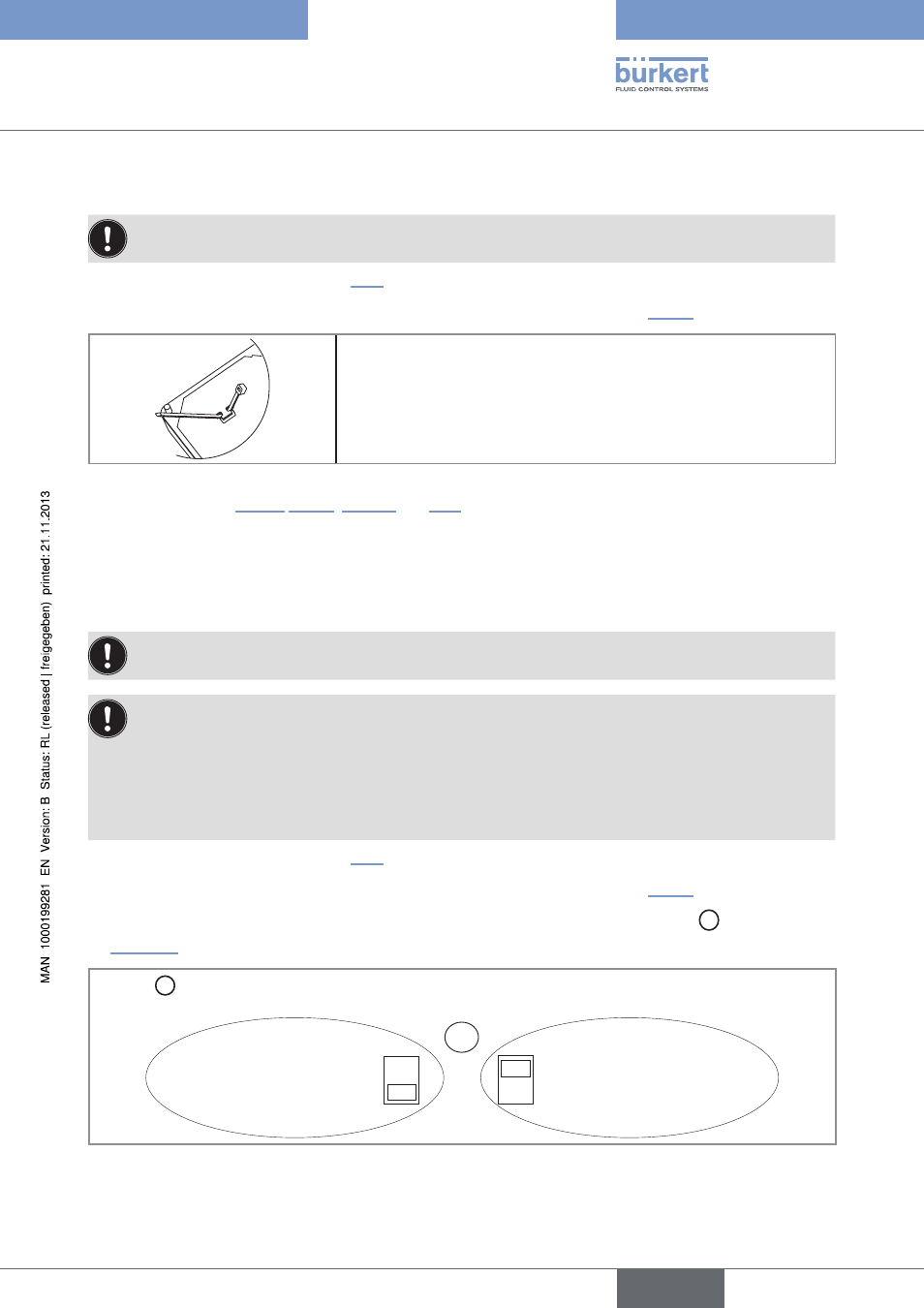
If the wall-mounted version is energized with a 115/230 V AC power supply, set selector D
as shown in
Selector D makes it possible to configure the supply voltage of the device in a 115/230 V AC version.
→
Energize the device with a
230 V AC voltage.
→
Energize the device with a
115 V AC voltage.
D
230V
115V
Figure 26:
Selector of the supply voltage on a 115/230 V AC version
→
Loosen the nuts of the cable glands.
English
Type 8025 - 8035 BATCH