Test outputs (test out) – Dynasonics DXN Portable Ultrasonic Measurement System User Manual
Page 67
The I/O>Scale Out sets the parameter the output circuitry will respond to. Choices for Data To Output are either Flow or Power.
Additionally this screen sets the minimum and maximum values the outputs will be scaled to.
NOTE:
N
Transit time measurements are capable of bidirectional flow but Doppler is not. The only time setting the Flow at Min
Out to a negative value may be necessary is if the meter stays in transit time mode. If the meter is used in Doppler
mode exclusively or when in hybrid mode the meter switches to Doppler mode, set the value for Flow at Min Out no
lower than zero.
An example of a valid use of setting Flow at Min Out below zero would be a transit time application where flow can be in
either the forward or reverse direction. If for instance a tap water system is capable of 100 gpm forward and 100 gpm in
reverse then setting the Flow at Min Out to -100 and Flow at Max Out to +100 would be valid entries.
If the meter were programed to output a 4-20 mA signal then 4 mA would represent –100 gpm and 20 mA would indicate
+100 gpm. The zero flow point would be indicated as 12 mA (halfway between 4 mA and 20 mA).
-100
100
-50
50
0
GPM
4 mA
20 mA
8 mA
16 ma
12 mA
mA
Dead
Band
Figure 86: Bidirectional current output
Also keep in mind that no flowmeter can read down to zero. There is going to be a small dead band around true zero where
the velocity of the fluid is not great enough for the meter to register. The absolute minimum under perfect conditions is 0.1
fps (0.03 mps). Whatever flow rates these velocities correspond to will be the minimum dead band around true zero.
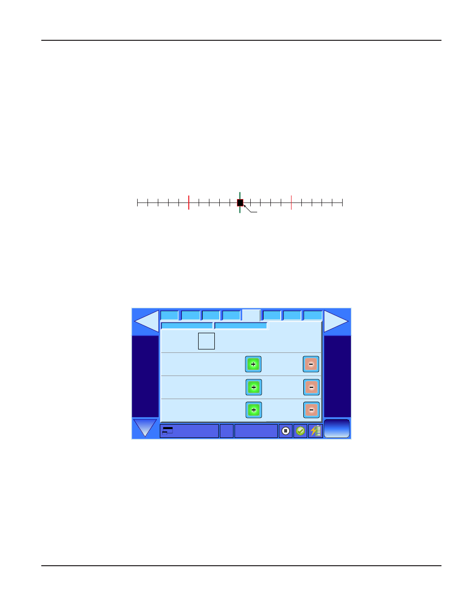
Test Outputs (Test Out)
Site Name
0.00 GPM
3/28/2012
13:24
I/O
Display
Adv
Cal
System
Site
Meter
Log
Test Out
Test Frequency Out (Hz)
20
Test 4-20 mA Out (mA)
4.000
Test 0 - 10V Out (V)
0.000
Enter Output Test Mode
Scale Out
Set Out
Figure 87: Test Outputs Setup
Test Out is used to calibrate devices connected to the DXN thru the I/O breakout box. To use this function first connect the
desired output to a device designed to read that type of output signal. For 4-20 mA out use a milliammeter. For the 0...10V DC
output use a voltmeter and for the frequency output either a frequency counter or oscilloscope is necessary.
Next using the + and - buttons select the output level to calibrate to. For example common test levels for the 4-20 mA output
are 4, 8, 12, 16, and 20 mA.
Finally put a check mark in the Enter Output Test Mode box to activate the outputs.
Installation & Operation Manual
Page 67
February 2013