Manual mode operation, Outputs, A series – GE Industrial Solutions A Series Lighting Control Panelboards Programmer User Guide User Manual
Page 25
A Series
®
Lighting Controller LCD Programmer
Chapter 8 – Lighting Group Menu
21
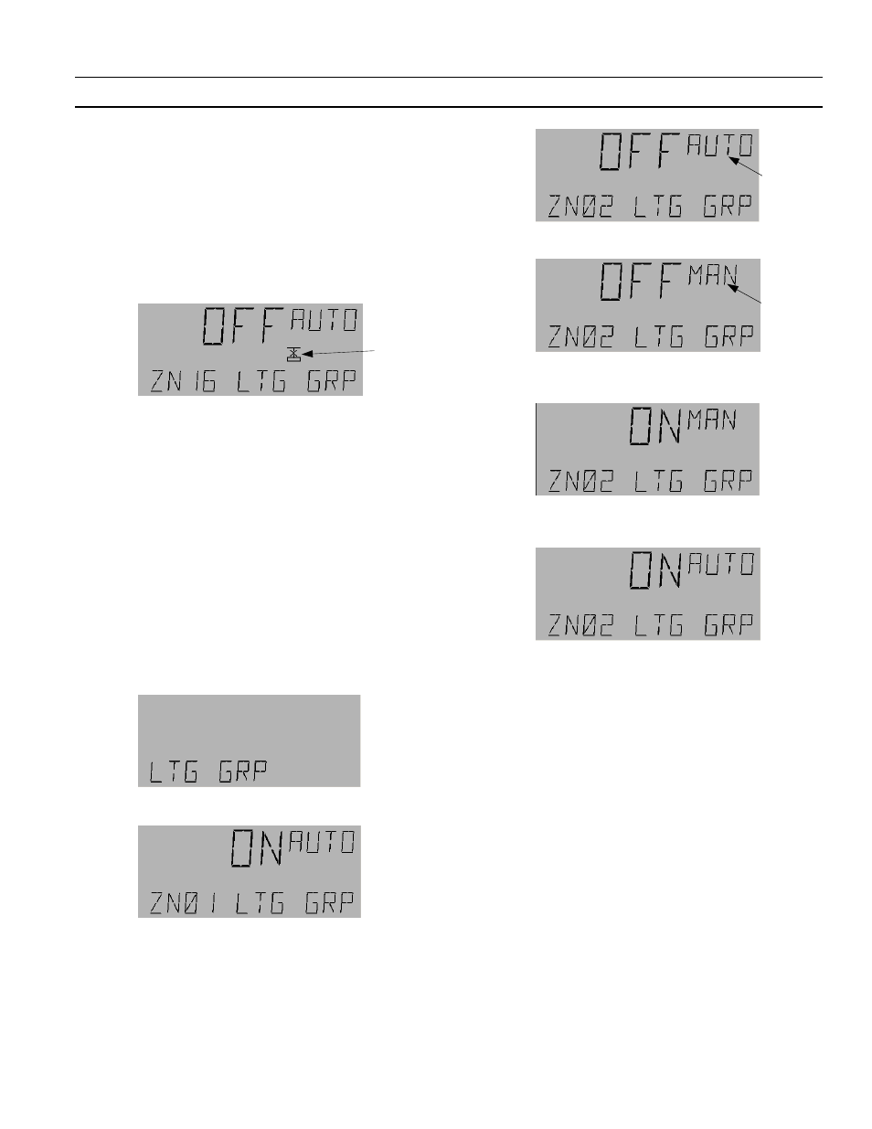
The Lighting Group menu is used to control and
configure the 16 lighting groups, ZN01 to ZN16. These
groups can be operated in auto and manual modes;
manual mode has higher priority. A group indicates
fault mode if the switch is linked to the group is not in
the network. For example, if the switch MI101 has been
linked to the group ZN16 LTG GRP and the Linknet
device (standard expansion board) is not in the
network, the group indicates a fault condition, as
shown:
Within each Lighting Group (ZN01 to) menu there are
six main submenus:
• Outputs
• Schedule
• Astro
• Photocell
• Override
• Groups
The following sections describe how to set up a lighting
group and access the six submenus.
Manual Mode Operation
To operate a group in manual mode, do the following:
1.
Navigate to the Lighting Group menu:
2.
Press
OK
to display the first lighting group (ZN01):
3.
Use the arrow keys to scroll to the desired group
and press
OK
to select it. For example, if Lighting
Group 2 (ZN02 LTG GRP) is selected, the display
is as follows:
4.
Press the
A/M
key to switch to manual mode:
5.
Use the arrow keys to change OFF to ON or ON to
OFF and press
OK
to accept the change:
6.
To return to auto mode, press
OK
, followed by the
A/M
key and
OK
again:
7.
Press
E S C
as needed to return to the desired
previous menu.
Outputs
Lighting Outputs can be either local or remote
references of Binary Outputs (BOs) or Lighting Groups
(LGs). The Programmer is used to tell the LG what
lighting outputs (BO/LG) to control. (Note that
Lighting Groups cannot reference themselves.) With
each output a local or remote switch can be linked. The
switch can be a physical one (MI type) or a binary
variable (BV), whose values can be changed with the
keypad. The BV variables are accessible using the
Breaker Override menu of the Programmer.
The switch controls individual breakers/group On and
Off. For each lighting output entered, an optional
switch can be assigned to control the individual breaker
On and Off. Switch references to BI and MV should be
ignored.
Fault
Symbol
Flashing
Flashing