Lighting switches, A series – GE Industrial Solutions A Series Lighting Control Panelboards Programmer User Guide User Manual
Page 21
A Series
®
Lighting Controller LCD Programmer
Chapter 7 – I/O Menu
17
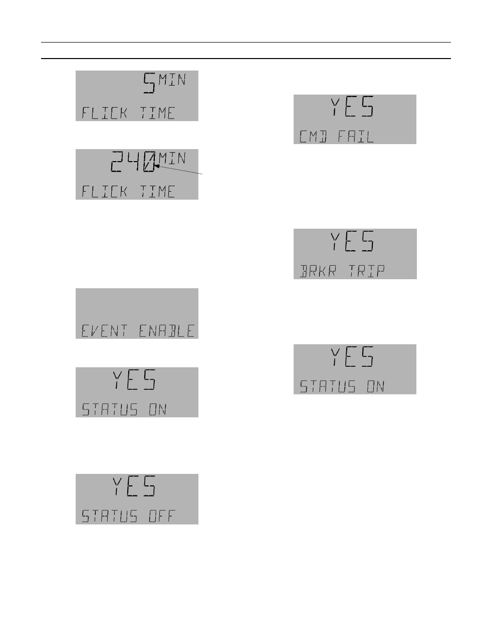
4.
Press
OK
to adjust the time. Use the number
keypad to adjust a Flick Time from 1–240 minutes.
5.
Press
OK
to accept the change. Press
ESC
and then
the down arrow to continue to Event Enable.
Editing Event Enable
Event Enable is used to enable the breaker events to be
captured in compact event log. Use the following
procedure to edit Event Enable:
1.
From the Event Enable submenu press
OK
.
2.
Press
OK
to edit; YES or NO STATUS ON appears
on the display.
YES/NO STATUS ON enables or disables,
respectively, the recording (in the CEL) of a
breaker when it changes to ON.
3.
Use the arrow keys to select No or Yes and then
press
OK
. Press
OK
again to edit.
YES/NO STATUS OFF enables or disables,
respectively, the recording (in the CEL) of a
breaker when it changes to OFF condition.
4.
Use the arrow keys to select No or Yes. Press
OK
to
accept any change.
5.
The Command Failure submenu is displayed;
press
OK
to edit.
YES or NO CMD FAIL enables or disables the
recording (in the CEL) of the CMD event A CMD
event occurs when the breaker is ON and it is
commanded to turn OFF.
6.
Use the arrow keys to select No or Yes. Press
OK
to
accept any change.
7.
No or Yes Breaker Trip is displayed; press
OK
to
edit.
Breaker Trip enables or disables the recording (in
the CEL) of a breaker going to trip position from
ON.
8.
Use the arrow keys to select No or Yes. Press
OK
to
accept any change; the menu rolls back to the
Status On screen.
9.
Use the arrow keys to scroll through the changes
or press
ESC
to return to the Event Enable
submenu. Press
ESC
as needed to return to the
desired previous menu.
Lighting Switches
Lighting switches are maintained and momentary
switches mounted on the standard/remote input
expansion board. Maintained switches are defined by
the states ON, OFF, and N/A. N/A means that the
switch is not present on the board. Momentary switches
are toggling switches. When the switch is turned on, it
toggles its state. There are 66 switches, LTG SW
101–116, 201–216, 301–316, 401–416, and 501–502.
LTG SW 101–116 are mounted on the standard input
expansion module which is on the main controller and
LTG SW 201–216, 301–316, 401–416, and 501–502 are
controlled from the remote expansion module. (Please
refer to DEH41083 for further information). Each
Flashing