Min. current at low speed is, H-70 warning current low, H-71 warning current high – GE Industrial Solutions AF-650 GP General Purpose Drive Programming Guide User Manual
Page 68: H-70 warning, Current low, H-71 warning current, High, 6 h-7# adjustable warnings
H-61 High Speed Load Compensation
Range:
Function:
100 %
*
[0 - 300
%]
Enter the % value to compensate voltage in
relation to load when the motor is running
at high speed and obtain the optimum U/f
characteristic. The motor size determines
the frequency range within which this
parameter is active.
Motor size
Change-over
0.25 kW - 7.5 kW
> 10 Hz
Table 3.14
H-64 Resonance Dampening
Range:
Function:
100 %
*
[0 - 500
%]
Enter the resonance dampening value. Set
H-65 Resonance Dampening Time Constant to
help eliminate high-frequency resonance
problems. To reduce resonance oscillation,
increase the value of H-64 Resonance
NOTE
H-64 Resonance Dampening will not have effect when
P-20 Motor Construction = [1] PM, non salient SPM.
H-65 Resonance Dampening Time Constant
Range:
Function:
5 ms
*
[5 - 50 ms] Set H-64 Resonance Dampening and
H-65 Resonance Dampening Time Constant to
help eliminate high-frequency resonance
problems. Enter the time constant that
provides the best dampening.
NOTE
H-65 Resonance Dampening Time Constant will not have
effect when P-20 Motor Construction = [1] PM, non salient
SPM.
H-66 Min. Current at Low Speed
Range:
Function:
100
%
*
[1 -
200 %]
Enter the minimum motor current at low speed,
see H-53 Model Shift Frequency. Increasing this
current improves motor torque at low speed.
H-66 Min. Current at Low Speed is enabled when
H-40 Configuration Mode [0] Speed open loop only.
The frequency converter runs with constant
current through motor for speeds below 10 Hz.
For speeds above 10 Hz, the motor flux model in
the frequency converter controls the motor.
F-40 Torque Limiter (Driving) and/or F-41 Torque
Limiter (Braking) automatically adjust H-66 Min.
Current at Low Speed. The parameter with the
H-66 Min. Current at Low Speed
Range:
Function:
highest value adjusts H-66 Min. Current at Low
Speed. The current setting in H-66 Min. Current at
Low Speed is composed of the torque generating
current and the magnetizing current.
Example: Set F-40 Torque Limiter (Driving) to 100%
and set F-41 Torque Limiter (Braking) to 60%.
H-66 Min. Current at Low Speed automatically
adjusts to about 127%, depending on the motor
size.
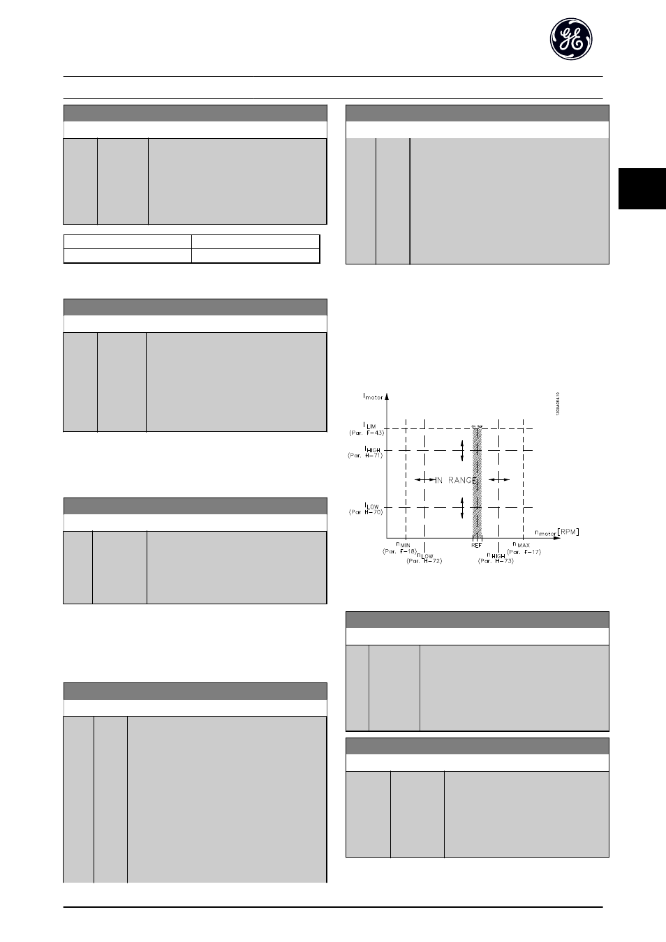
3.7.6 H-7# Adjustable Warnings
Parameters to configure the warnings limits for current,
speed, reference, and feedback.
Warnings are shown on the keypad, and can be
programmed to be outputs or to be read out via serial bus
in the Extended Status Word.
Illustration 3.31 Adjustable Warnings
H-70 Warning Current Low
Range:
Function:
0 A
*
[0 - par.
H-71 A]
Enter the I
LOW
value. When the motor current
falls below this limit, the display reads Current
Low. The signal outputs can be programmed
to produce a status signal on terminal 27 or
29 and on relay output 01 or 02. Refer to
H-71 Warning Current High
Range:
Function:
par.
DR-37 A
*
[par. H-70
- par. DR-37
A]
Enter the I
HIGH
value. When the motor
current exceeds this limit, the display
reads Current High. The signal outputs
can be programmed to produce a status
signal on terminal 27 or 29 and on relay
output 01 or 02. Refer to Illustration 3.31.
Parameter Descriptions
AF-650 GP Programming Guide
DET-618C
67
3
3