GE Industrial Solutions AF-650 GP General Purpose Drive Programming Guide User Manual
Page 128
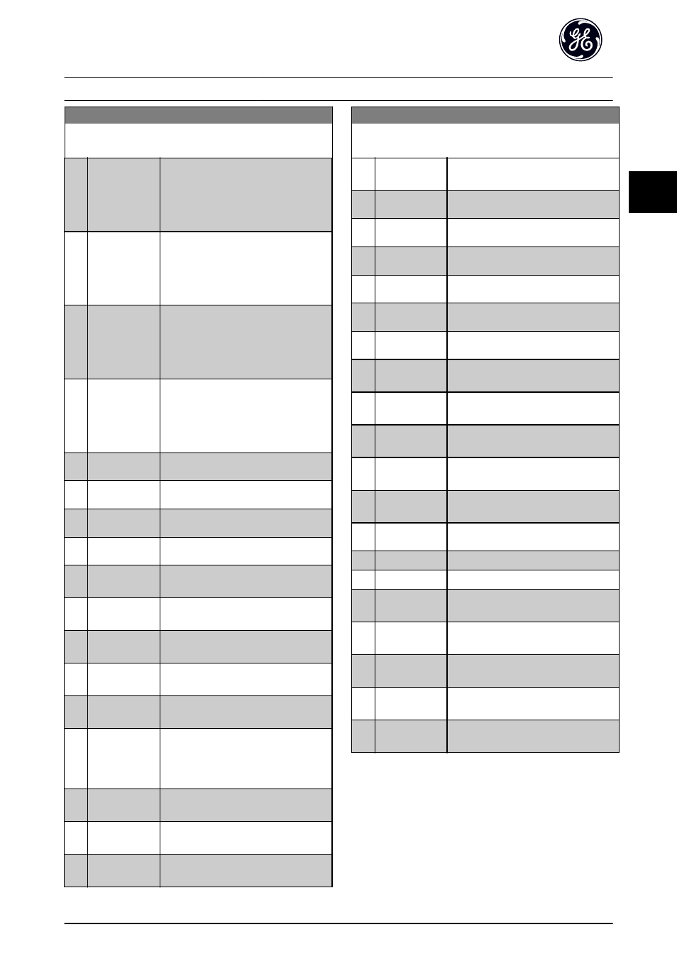
LC-52 Logic Controller Action
Array [20]
Option:
Function:
[14]
Select preset ref
4
Selects preset reference 4.
If the active preset reference is changed,
it will merge with other preset reference
commands coming from either the digital
inputs or via a Network.
[15]
Select preset ref
5
Selects preset reference 5.
If the active preset reference is changed,
it will merge with other preset reference
commands coming from either the digital
inputs or via a Network.
[16]
Select preset ref
6
Selects preset reference 6.
If the active preset reference is changed,
it will merge with other preset reference
commands coming from either the digital
inputs or via a Network.
[17]
Select preset ref
7
Selects preset reference 7.
If the active preset reference is changed,
it will merge with other preset reference
commands coming from either the digital
inputs or via a Network.
[18]
Select Accel/
Decel 1
Selects ramp 1.
[19]
Select Accel/
Decel 2
Selects ramp 2.
[20]
Select Accel/
Decel 3
Selects ramp 3.
[21]
Select Accel/
Decel 4
Selects ramp 4.
[22]
Run
Issues a start command to the frequency
converter.
[23]
Run reverse
Issues a start reverse command to the
frequency converter.
[24]
Stop
Issues a stop command to the frequency
converter.
[25]
Qstop
Issues a quick stop command to the
frequency converter.
[26]
Dcstop
Issues a DC stop command to the
frequency converter.
[27]
Coast
The frequency converter coasts
immediately. All stop commands
including the coast command stop the
Logic Controller.
[28]
Freeze output
Freezes the output frequency of the
frequency converter.
[29]
Start timer 0
Starts timer 0, see LC-20 Logic Controller
Timer for further description.
[30]
Start timer 1
Starts timer 1, see LC-20 Logic Controller
Timer for further description.
LC-52 Logic Controller Action
Array [20]
Option:
Function:
[31]
Start timer 2
Starts timer 2, see LC-20 Logic Controller
Timer for further description.
[32]
Set digital out A
low
Any output with LC output A will be low.
[33]
Set digital out B
low
Any output with LC output B will be low.
[34]
Set digital out C
low
Any output with LC output Cwill be low.
[35]
Set digital out D
low
Any output with LC output D will be low.
[36]
Set digital out E
low
Any output with LC output E will be low.
[37]
Set digital out F
low
Any output with LC output F will be low.
[38]
Set digital out A
high
Any output with LC output A will be
high.
[39]
Set digital out B
high
Any output with LC output B will be
high.
[40]
Set digital out C
high
Any output with LC output C will be
high.
[41]
Set digital out D
high
Any output with LC output D will be
high.
[42]
Set digital out E
high
Any output with LC output E will be
high.
[43]
Set digital out F
high
Any output with LC output Fwill be high.
[60]
Reset Counter A
Resets Counter A to zero.
[61]
Reset Counter B
Resets Counter B to zero.
[70]
Start timer 3
Start Timer 3, see LC-20 Logic Controller
Timer for further description.
[71]
Start timer 4
Start Timer 4, see LC-20 Logic Controller
Timer for further description.
[72]
Start timer 5
Start Timer 5, see LC-20 Logic Controller
Timer for further description.
[73]
Start timer 6
Start Timer 6, see LC-20 Logic Controller
Timer for further description.
[74]
Start timer 7
Start Timer 7, see LC-20 Logic Controller
Timer for further description.
Parameter Descriptions
AF-650 GP Programming Guide
DET-618C
127
3
3