22 sf-# special functions – GE Industrial Solutions AF-650 GP General Purpose Drive Programming Guide User Manual
Page 140
3.22 SF-#
Special
Functions
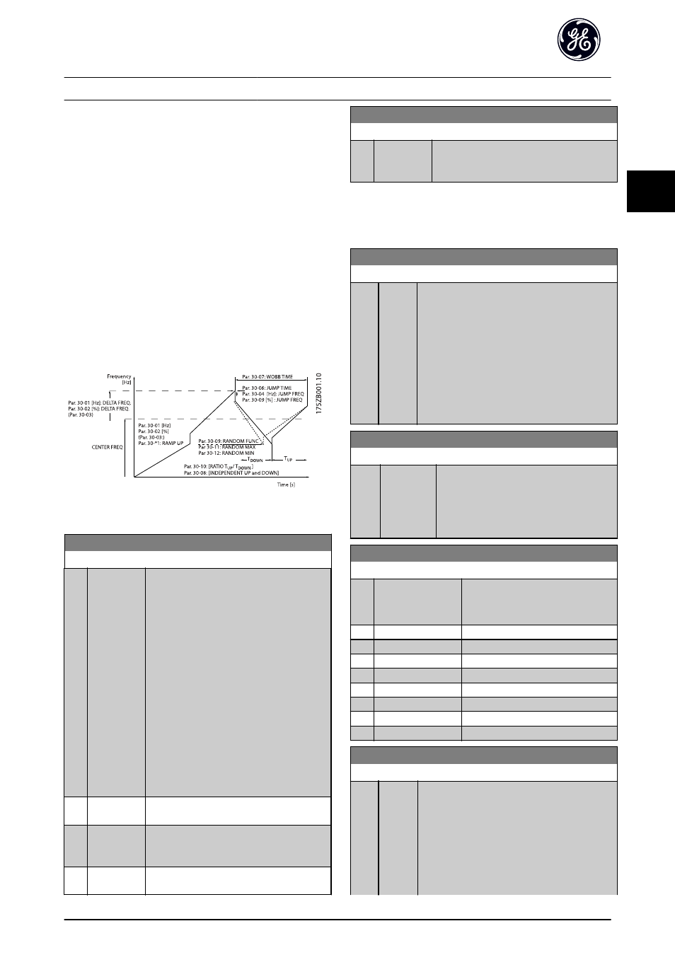
3.22.1 SF-## Wobble Function
The wobble function is primarily used for synthetic yarn
winding applications. The wobble option is to be installed
in the frequency converter controlling the traverse drive.
The traverse drive frequency converter will move the yarn
back and forth in a diamond pattern across the surface of
the yarn package. To prevent a buildup of yarn at the
same points at the surface, this pattern must be altered.
The wobble option can accomplish this by continuously
varying the traverse velocity in a programmable cycle. The
wobble function is created by superimposing a delta
frequency around a center frequency. To compensate for
the inertia in the system a quick frequency jump can be
included. Especially suitable for elastic yarn applications
the option features a randomized wobble ratio.
Illustration 3.48 Wobble Function
SF-00 Wobble Mode
Option:
Function:
NOTE
This parameter cannot be adjusted
while running.
The standard speed open loop mode in
H-40 Configuration Mode is extended with a
wobble function. In this parameter it is
possible to select which method to be used
for the wobbler. The parameters can be set
as absolute values (direct frequencies) or as
relative values (percentage of other
parameter). The wobble cycle time can be
set as an absolute alue or as independent
up- and down times. When using an
absolute cycle time, the up- and down times
are configured through the wobble ratio.
[0]
*
Abs. Freq.,
Abs. Time
[1]
Abs. Freq.,
Up/ Down
Time
[2]
Rel. Freq.,
Abs. Time
SF-00 Wobble Mode
Option:
Function:
[3]
Rel. Freq.,
Up/ Down
Time
NOTE
The setting of “Center Frequency” takes place via the
normal reference handling parameter group.
SF-01 Wobble Delta Frequency [Hz]
Range:
Function:
5 Hz
*
[0 - 25
Hz]
The delta frequency is determining the
magnitude of the wobble frequency. The delta
frequency is superimposed on the center
frequency. SF-01 Wobble Delta Frequency [Hz] is
selecting both the positive and negative delta
frequency. The setting of SF-01 Wobble Delta
Frequency [Hz] must thus not be higher than the
setting of the center frequency. The initial ramp
up time from standstill until the wobble
sequence is running is determined.
SF-02 Wobble Delta Frequency [%]
Range:
Function:
25 %
*
[0 - 100 %] The delta frequency can also be expressed
as percentage of the center frequency and
can thus be maximum 100%. The function
is the same as for SF-01 Wobble Delta
SF-03 Wobble Delta Freq. Scaling Resource
Option:
Function:
Select which drive input should be
used to scale the delta frequency
setting.
[0]
*
No function
[1]
Analog Input 53
[2]
Analog Input 54
[3]
Frequency input 29
[4]
Frequency input 33
[7]
Analog Input X30/11
[8]
Analog Input X30/12
[15]
Analog Input X48/2
SF-04 Wobble Jump Frequency [Hz]
Range:
Function:
0 Hz
*
[0 -
20.0 Hz]
The jump frequency is used to compensate for
the inertia in the traverse system. If a jump in
the output frequency is required in the top and
in the bottom of the wobble sequence, the
frequency jump is set in this parameter. If the
traverse system has a very high inertia a high
jump frequency may create a torque limit
warning or trip (warning/alarm 12) or an over
Parameter Descriptions
AF-650 GP Programming Guide
DET-618C
139
3
3