GE Industrial Solutions AF-650 GP General Purpose Drive Programming Guide User Manual
Page 28
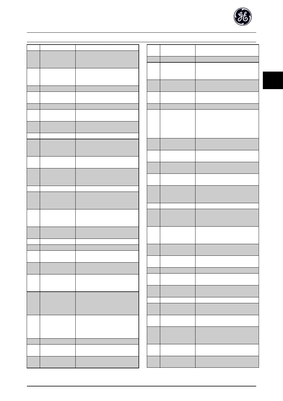
[1200] Control Word
Present control word
[1201] Reference [Unit]
Total reference (sum of digital/
analog/preset/bus/freeze ref./catch
up and slow-down) in selected unit.
[1202] Reference %
Total reference (sum of digital/
analog/preset/bus/freeze ref./catch
up and slow-down) in percent.
[1203] Status Word
Present status word.
[1205] Main Actual Value
[%]
Actual value as a percentage.
[1209] Custom Readout
[1210] Power [kW]
Actual power consumed by the
motor in kW.
[1211] Power [hp]
Actual power consumed by the
motor in HP.
[1212] Motor Voltage
Voltage supplied to the motor.
[1213] Frequency
Motor frequency, i.e. the output
frequency from the frequency
converter in Hz
[1214] Motor Current
Phase current of the motor
measured as effective value.
[1215] Frequency [%]
Motor frequency, i.e. the output
frequency from the frequency
converter in percent.
[1216] Torque
Actual motor torque in Nm
[1217] Speed [RPM]
Speed in RPM (revolutions per
minute) i.e. the motor shaft speed in
closed loop.
[1218] Motor Thermal
Thermal load on the motor,
calculated by the Electronic Thermal
Overload function.
[1219] KTY Sensor
Temperature
[1220] Motor Angle
[1221] Phase Angle
[1222] Torque %
Present motor load as a percentage
of the rated motor torque.
[1230] DC Link Voltage
Intermediate circuit voltage in the
frequency converter.
[1232] BrakeEnergy/s
Present brake power transferred to
an external brake resistor.
Stated as an instantaneous value.
[1233] BrakeEnergy/2 min
Brake power transferred to an
external brake resistor. The mean
power is calculated continuously for
the most recent 120 seconds.
[1234] Heatsink Temp.
Present heat sink temperature of the
frequency converter. The cut-out
limit is 95
±5 ±°C; cutting back in
occurs at 70
±5° C.
[1235] Inverter Thermal
Percentage load of the inverters.
[1236] Inv. Nom. Current
Nominal current of the frequency
converter.
[1237] Inv. Max. Current
Maximum current of the frequency
converter.
[1238] Logic Controller
State
State of the event executed by the
control.
[1239] Control Card Temp.
Temperature of the control card.
[1250] External Reference
Sum of the external reference as a
percentage, i.e. the sum of analog/
pulse/bus.
[1251] Pulse Reference
Frequency in Hz connected to the
digital inputs (18, 19 or 32, 33).
[1252] Feedback [Unit]
Reference value from programmed
digital input(s).
[1253] Digi Pot Reference
[1260] Digital Input
Signal states form the 6 digital
terminals (18, 19, 27, 29, 32 and 33).
Input 18 corresponds to the bit at
the far left. Signal low = 0; Signal
high = 1.
[1261] Terminal 53 Switch
Setting
Setting of input terminal 54. Current
= 0; Voltage = 1.
[1262] Analog Input 53
Actual value at input 53 either as a
reference or protection value.
[1263] Terminal 54 Switch
Setting
Setting of input terminal 54. Current
= 0; Voltage = 1.
[1264] Analog Input 54
Actual value at input 54 either as
reference or protection value.
[1265] Analog Output 42
[mA]
Actual value at output 42 in mA.
Use AN-50 Terminal 42 Output to
select the value to be shown.
[1266] Digital Output [bin]
Binary value of all digital outputs.
[1267] Freq. Input #29 [Hz] Actual value of the frequency
applied at terminal 29 as an impulse
input.
[1268] Freq. Input #33 [Hz] Actual value of the frequency
applied at terminal 33 as an impulse
input.
[1269] Pulse Output #27
[Hz]
Actual value of impulses applied to
terminal 27 in digital output mode.
[1270] Pulse Output #29
[Hz]
Actual value of impulses applied to
terminal 29 in digital output mode.
[1271] Relay Output [bin]
[1272] Counter A
Application dependent (e.g. LC
Control)
[1273] Counter B
Application dependent (e.g. LC
Control)
[1274] Prec. Stop Counter
Display the actual counter value.
[1275] Analog input
X30/11
Actual value at input X30/11 either
as reference or protection value.
[1276] Analog input
X30/12
Actual value at input X30/12 either
as reference or protection value.
[1277] Analog output
X30/8 mA
Actual value at output X30/8 in mA.
Use AN-60 Terminal X30/8 Output to
select the value to be shown.
[1280] Fieldbus CTW 1
Control word (CTW) received from
the Bus Master.
[1282] Fieldbus REF 1
Main reference value sent with
control word from the Bus Master.
Parameter Descriptions
AF-650 GP Programming Guide
DET-618C
27
3
3