3 k-2# keypad display – GE Industrial Solutions AF-650 GP General Purpose Drive Programming Guide User Manual
Page 27
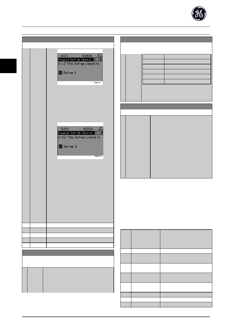
K-12 This Set-up Linked to
Option:
Function:
Illustration 3.2 Set-up 1
OR
2. While still in Set-up 1, copy Set-up 1 to Set-
up 2. Then set K-12 This Set-up Linked to to [2]
Set-up 2. This will start the linking process.
Illustration 3.3 Set-up 2
After the link is complete, K-13 Readout: Linked
Set-ups will read {1,2} to indicate that all ‘not
changeable during operation’ parameters are
now the same in Set-up 1 and Set-up 2. If there
are changes to a ‘not changeable during
operation’ parameter, e.g. P-30 Stator Resistance
(Rs), in Set-up 2, they will also be changed
automatically in Set-up 1. A switch between
Set-up 1 and Set-up 2 during operation is now
possible.
[0]
*
Not linked
[1]
Set-up 1
[2]
Set-up 2
[3]
Set-up 3
[4]
Set-up 4
K-13 Readout: Linked Set-ups
Array [5]
Range:
Function:
0
*
[0 - 255] View a list of all the set-ups linked by means of
K-12 This Set-up Linked to. The parameter has one
index for each parameter set-up. The parameter
value displayed for each index represents which
set-ups are linked to that parameter set-up.
K-13 Readout: Linked Set-ups
Array [5]
Range:
Function:
Index
Keypad value
0
{0}
1
{1,2}
2
{1,2}
3
{3}
4
{4}
Table 3.4 Example: Set-up 1 and Set-up 2 are
linked
K-14 Readout: Edit Set-ups / Channel
Range:
Function:
0
*
[-2147483648 -
2147483647]
View the setting of K-11 Edit Set-up for each
of the four different communication
channels. When the number is displayed in
hex, as it is in the keypad, each number
represents one channel.
Numbers 1-4 represent a set-up number; ‘F’
means factory setting; and ‘A’ means active
set-up. The channels are, from right to left:
keypad, Drive bus, USB, HPFB1-5.
Example: The number AAAAAA21h means
that the Drive bus selected Set-up 2 in
K-11 Edit Set-up, the keypad selected Set-up
1 and all others used the active set-up.
3.2.3 K-2# Keypad Display
Define the variables displayed in the keypad.
NOTE
Please refer to K-37 Display Text 1, K-38 Display Text 2 and
K-39 Display Text 3 for information on how to write display
texts.
Select a variable for display in line 1,
left position. The options are the
same as listed for parameter group
K-2#.
[0]
None
No display value selected.
[953]
Profibus Warning
Word
[2205] Readout Transmit
Error Counter
[2206] Readout Receive
Error Counter
[2207] Readout Bus Off
Counter
[2213] Warning Parameter
[1501] Running Hours
[1502] kWh Counter
Parameter Descriptions
AF-650 GP Programming Guide
26
DET-618C
3
3