GE Industrial Solutions AF-650 GP General Purpose Drive Programming Guide User Manual
Page 123
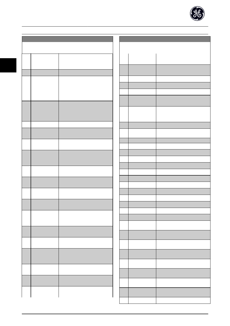
LC-10 Comparator Operand
Array [6]
Option:
Function:
[53]
Drive ready
The frequency converter is ready for
operation and applies a supply signal
on the control board.
[54]
Running
The motor is running.
[55]
Reversing
The output is high when the
frequency converter is running
counter clockwise (the logical product
of the status bits “running” AND
“reverse”).
[56]
In range
The motor is running within the
programmed current and speed
ranges set in H-70 Warning Current
Low to H-73 Warning Speed High.
[60]
On reference
The motor is running on reference.
[61]
Below reference,
low
The motor is running below the value
given in H-74 Warning Reference Low.
[62]
Above ref, high
The motor is running above the value
given in H-75 Warning Reference High
[65]
Torque limit
The torque limit, set in F-40 Torque
Limiter (Driving) or F-41 Torque Limiter
(Braking), has been exceeded.
[66]
Current Limit
The motor current limit, set in
F-43 Current Limit, has been exceeded.
[67]
Out of current
range
The motor current is outside the
range set in F-43 Current Limit.
[68]
Below I low
The motor current is lower than set in
[69]
Above I high
The motor current is higher than set
[70]
Out of speed
range
The speed is outside the range set in
[71]
Below speed low
The output speed is lower than the
setting in H-72 Warning Speed Low.
[72]
Above speed high
The output speed is higher than the
setting in H-73 Warning Speed High.
[75]
Out of feedback
range
The feedback is outside the range set
in H-76 Warning Feedback Low and
[76]
Below feedback
low
The feedback is below the limit set in
[77]
Above feedback
high
The feedback is above the limit set in
[80]
Thermal warning
The thermal warning turns on when
the temperature exceeds the limit in
LC-10 Comparator Operand
Array [6]
Option:
Function:
the motor, the frequency converter,
the brake resistor or thermistor.
[82]
Mains out of range The mains voltage is outside the
specified voltage range.
[85]
Warning
A warning is active.
[86]
Alarm (trip)
A (trip) alarm is active.
[87]
Alarm (trip lock)
A (Trip lock) alarm is active.
[90]
Bus OK
Active communication (no time-out)
via the serial communication port.
[91]
Torque limit &
stop
If the frequency converter has
received a stop signal and is at the
torque limit, the signal is logic “0”.
[92]
Brake fault (IGBT)
The brake IGBT is short circuited.
[93]
Mech. brake
control
The mechanical brake is active.
[94]
Safe stop active
[100] Comparator 0
The result of comparator 0.
[101] Comparator 1
The result of comparator 1.
[102] Comparator 2
The result of comparator 2.
[103] Comparator 3
The result of comparator 3.
[104] Comparator 4
The result of comparator 4.
[105] Comparator 5
The result of comparator 5.
[110] Logic rule 0
The result of Logic rule 0.
[111] Logic rule 1
The result of Logic rule 1.
[112] Logic rule 2
The result of Logic rule 2.
[113] Logic rule 3
The result of Logic rule 3.
[114] Logic rule 4
The result of Logic rule 4.
[115] Logic rule 5
The result of Logic rule 5.
[120] Logic Controller
Time-out 0
The result of LC timer 0.
[121] Logic Controller
Time-out 1
The result of LC timer 1.
[122] Logic Controller
Time-out 2
The result of LC timer 2.
[123] Logic Controller
Time-out 3
The result of LC timer 3.
[124] Logic Controller
Time-out 4
The result of LC timer 4.
[125] Logic Controller
Time-out 5
The result of LC timer 5.
[126] Logic Controller
Time-out 6
The result of LC timer 6.
[127] Logic Controller
Time-out 7
The result of LC timer 7.
[130] Digital input DI18
Digital input 18. High = True.
Parameter Descriptions
AF-650 GP Programming Guide
122
DET-618C
3
3