5 power connector, 2 leds, Table 2 leds – ZyXEL Communications VDSL SWITCH VES-1616F-3X User Manual
Page 40
Chapter 3 Hardware Overview
VES-1616F-3x Series User’s Guide
40
• VT100 terminal emulation
• 9600 bps
• No parity, 8 data bits, 1 stop bit
• No flow control
Connect the male 9-pin end of the console cable to the console port of the switch. Connect the
female end to a serial port (COM1, COM2 or other COM port) of your computer.
3.1.5 Power Connector
Make sure you are using the correct power source as shown on the panel.
"
Make sure that no objects obstruct the airflow of the fans.
3.2 LEDs
The LEDs are located on the front panel. The following table describes the LEDs on the front
panel.
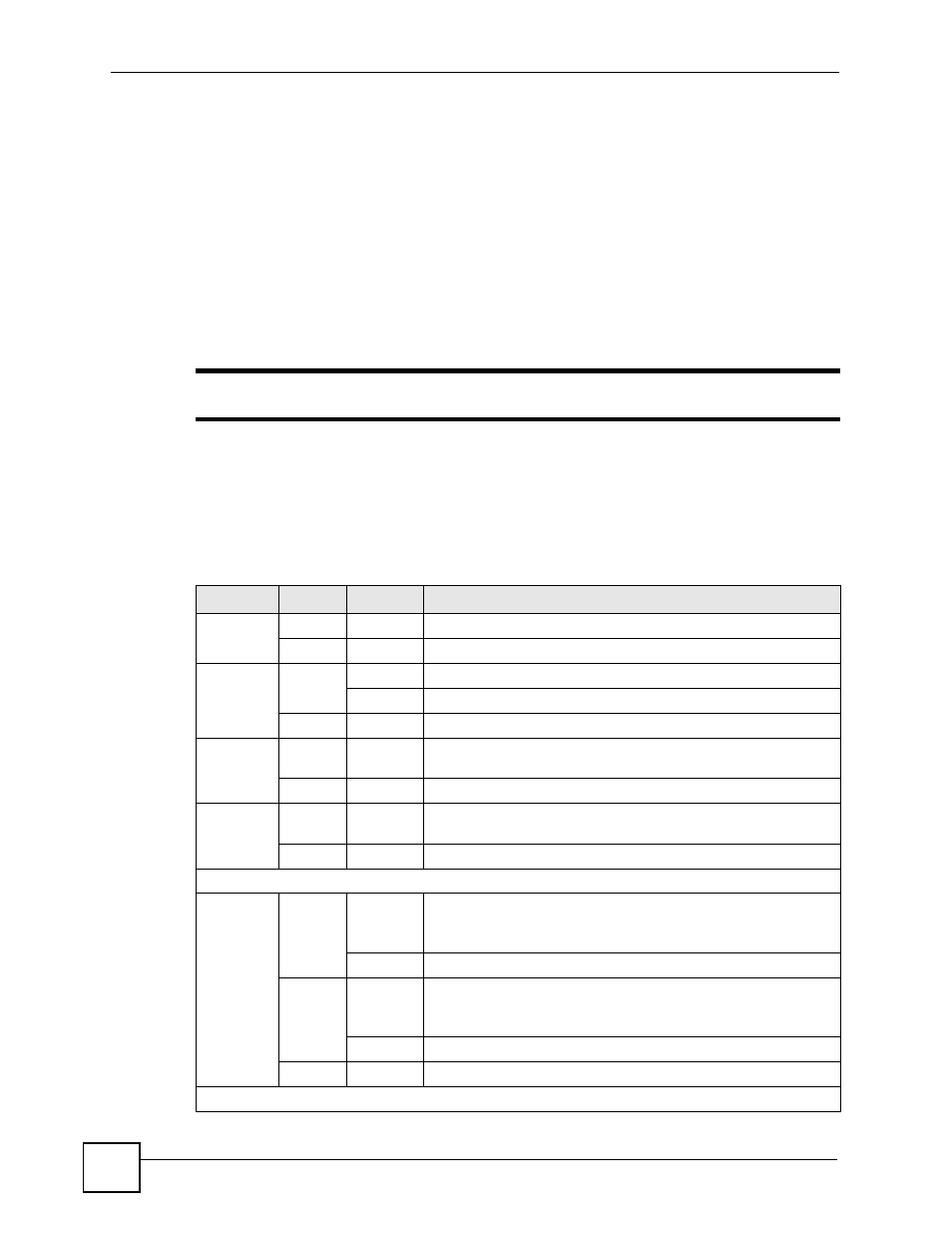
Table 2 LEDs
LED
COLOR
STATUS
DESCRIPTION
PWR
Green
On
The system is turned on.
Off
The system is off.
SYS
Green
Blinking
The system is rebooting and performing self-diagnostic tests.
On
The system is on and functioning properly.
Off
The power is off or the system is not ready or malfunctioning.
ALM
Red
On
There is a hardware failure (abnormal temperature, voltage or fan
speeds).
Off
The system is functioning normally.
VDSL
Green
On
The link to a VDSL line is up and the system is transmitting or
receiving to/from a VDSL link.
Off
The link to a VDSL line is down.
Gigabit Ports
LNK/ACT
Green
On
The link to a 10 Mbps Ethernet network is up.
The link to a 1000 Mbps Ethernet network is up if the amber LED
is on at the same time.
Blinking
The port is receiving or transmitting data at 10 Mbps
Amber
On
The link to a 100 Mbps Ethernet network is up.
The link to a 1000 Mbps Ethernet network is up if the green LED
is on at the same time.
Blinking
The port is receiving or transmitting data at 100 Mbps.
Off
The link to an Ethernet network is down.
Mini-GBIC Slots