Model 9720 and 9783 csu/dsu data port connector, Standard v.35 straight-through cable – Paradyne 9788 User Manual
Page 311
E. Connectors, Cables, and Pin Assignments
9700-A2-GB20-20
December 2002
E-7
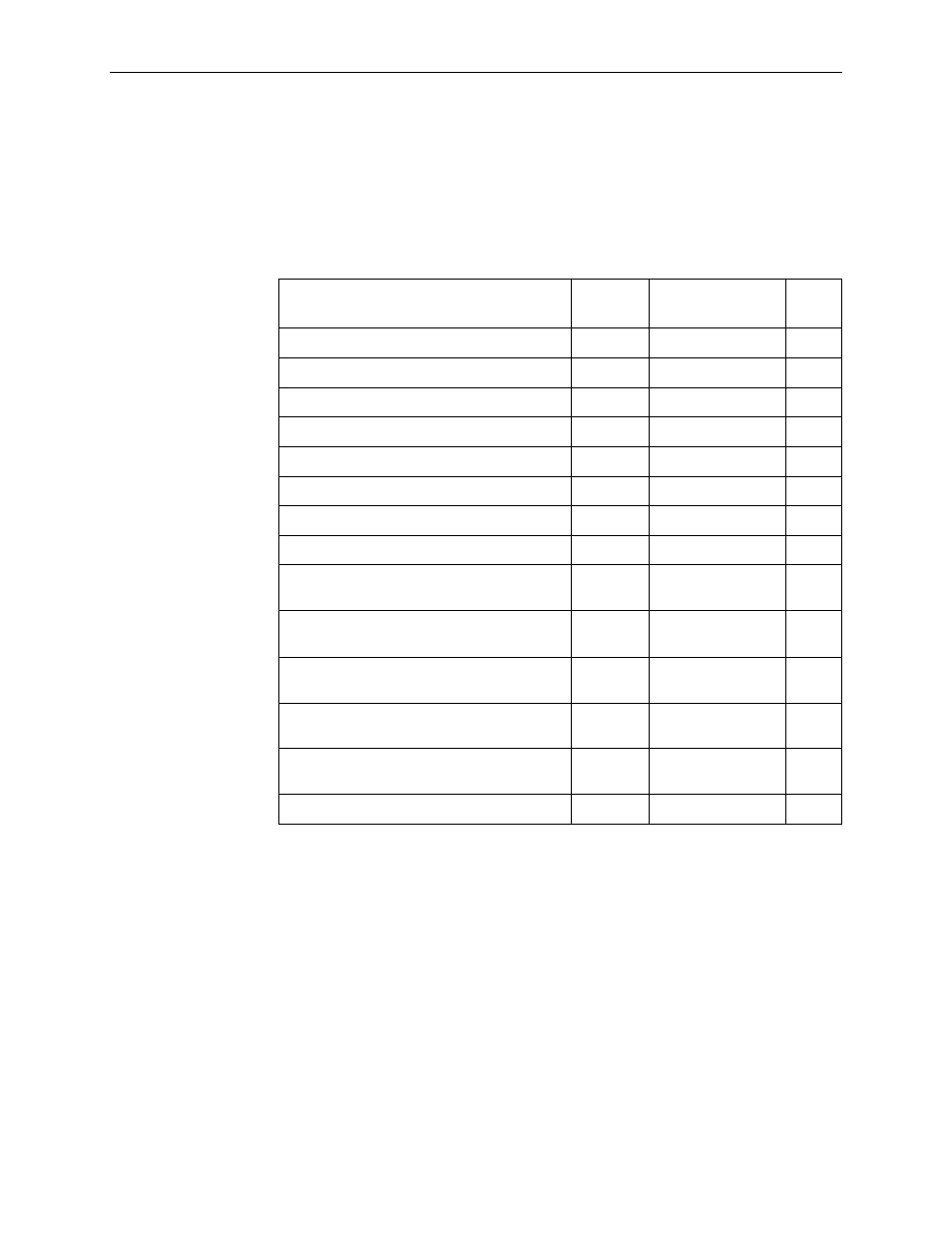
Model 9720 and 9783 CSU/DSU Data Port Connector
Table E-5, Model 9720 and 9783 CSU/DSU Data Port Connector
, provides the pin
assignments for the 34-position V.35 connector to the DTE.
This does not apply to the router.
Standard V.35 Straight-through Cable
A standard V.35 straight-through cable can be used to connect a DTE port to a
DTE, where a 34-pin plug-type connector is needed for the data port and a
34-position socket-type connector is needed for the DTE. No special-order cables
are required.
Table E-5.
Model 9720 and 9783 CSU/DSU Data Port Connector
Signal
ITU-T
Number
Direction
Pin
Shield
101
—
A
Signal Ground/Common
102
—
B
Request to Send (RTS)
105
To DSU (In)
C
Clear to Send (CTS)
106
From DSU (Out)
D
Data Set Ready (DSR)
107
From DSU (Out)
E
Receive Line Signal Detector (RLSD or LSD) 109
From DSU (Out)
F
Data Terminal Ready ( DTR)
108/1, /2
To DSU (In)
H
Local Loopback (LL)
141
To DSU (In)
L
Transmit Data (TXD)
103
To DSU (In)
P ( A)
S ( B)
Receive Data (RXD)
104
From DSU (Out)
R ( A)
T (B )
Transmit Signal Element Timing –
DTE Source (XTXC or TT)
113
To DSU (In)
U ( A)
W (B)
Receive Signal Element Timing –
DCE Source (RXC)
115
From DSU (Out)
V ( A)
X ( B)
Transmit Signal Element Timing –
DCE Source (TXC)
114
From DSU (Out)
Y ( A)
AA (B )
Test Mode Indicator (TM)
142
From DSU (Out)
NN