Pvc connection status – Paradyne 9788 User Manual
Page 160
7. Operation and Maintenance
7-24
December
2002
9700-A2-GB20-20
PVC Connection Status
PVC Connection Status is selected from the Status menu.
Main Menu
→Status→PVC Connection Status
PVC Connection Status Screen Example
Only PVC connections with an active Source DLCI configuration are shown. If the
No PVC Connections
message appears instead of a list of PVC connections,
no PVC connections have been configured yet.
Table 7-9.
PVC Connection Status Screen (1 of 2)
Field
Display
What It Indicates
Link
Identifies the cross-connection of source
and primary destination DLCIs configured
for the unit.
Net1-FR1
The frame relay link 1 is the
source/destination is on Network 1.
Net1-ATM
(9783, 9788)
The ATM link is the source/destination
on Network 1.
Port-1
(CSU/DSUs only)
The CSU/DSU’s user data port is the
source/destination
.
Mgmt PVC
Name
The virtual circuit is a management link
that terminates in the unit.
Name is the
link name.
Rtr-S0
(Routers only)
The source link is the virtual router’s
frame relay link, internally connected to
its Serial 0 interface.
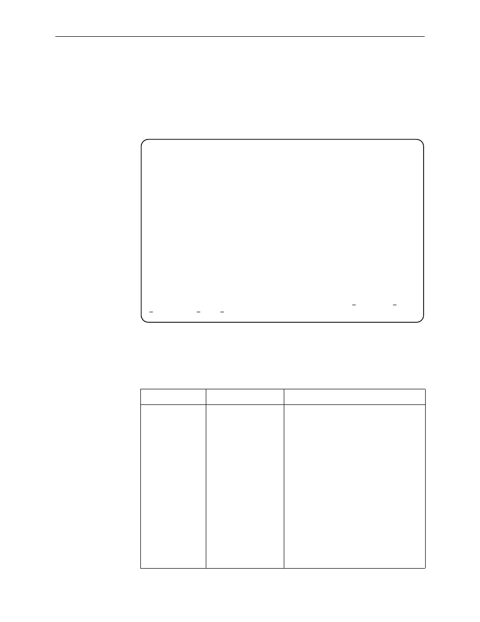
main/status/connections 9783-C-SLV
Device Name: Node A 06/05/2001 06:03
Page 1 of 2
PVC CONNECTION STATUS
Source Primary Destination
Link DLCI EDLCI Link DLCI EDLCI Status
Port-1 201 Net1-FR1 300 PM Active
Port-1 202 Net1-FR1 1001 0 Active
Port-1 100 Net1-FR1 1001 2 Active
Port-1 204 Net1-FR1 1001 2 Active
Rrt-S0 204 Net1-FR1 206 0 Active
Mgmt PVC Port-1 16 Active
Mgmt PVC TS_Mgmt Net1-ATM (0, 35) Active
Mgmt PVC Largo Net1-ATM (0, 33) Active
--------------------------------------------------------------------------------
ESC for previous menu MainMenu Exit
Refresh PgUp PgDn