Ldm cabling information, Ldu flying lead connector pinouts, Cable diagram – Perle Systems RIO 5500036-17 User Manual
Page 184: Mini din on rio link flying lead, Cable diagram mini din on rio link flying lead
RIO Remote I/O System User Guide
Installing a Long Distance Module (LDM)
Page 184
Chapter 2 Installing hardware and software
LDM Cabling information
This section contains cabling information for installing Long Distance Modules.
LDU flying lead connector pinouts
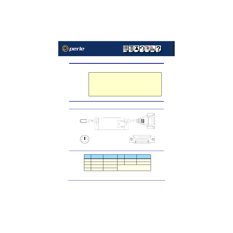
Cable diagram
Mini DIN on RIO link flying lead
Note
For modem installations, a converter cable must be used to connect the LDU DB25 flying
lead to the modem. See
Asynchronous/Synchronous Modem & X21bis (DB25
On long-wire installations, you can connect the long wire directly to the DB25 flying lead.
See
Asynchronous Long-wire Connection (DB25 male to DB25 male)
.
For X.21 Synchronous connections, you need to use a converter cable to connect the DB25
flying lead to the X21 interface. See
PIn
Signal
Description
PIn
Signal
Description
1
GND
Ground
5
RXD+
Receive Data
2
VCC
Supply Voltage
6
TXD+
Transmit Data
3
RXD-
Inverse RXD
4
TXD-
Inverse TXD
1
2
3
4
5
6
1
13
14
25