2 control 2 register (ctrl2), 2 control 2 register (ctrl2) -5, 1 ctrl2 under sequential scan modes – Freescale Semiconductor ColdFire MCF52210 User Manual
Page 441
Analog-to-Digital Converter (ADC)
MCF52211 ColdFire® Integrated Microcontroller Reference Manual, Rev. 2
Freescale Semiconductor
26-5
26.4.2
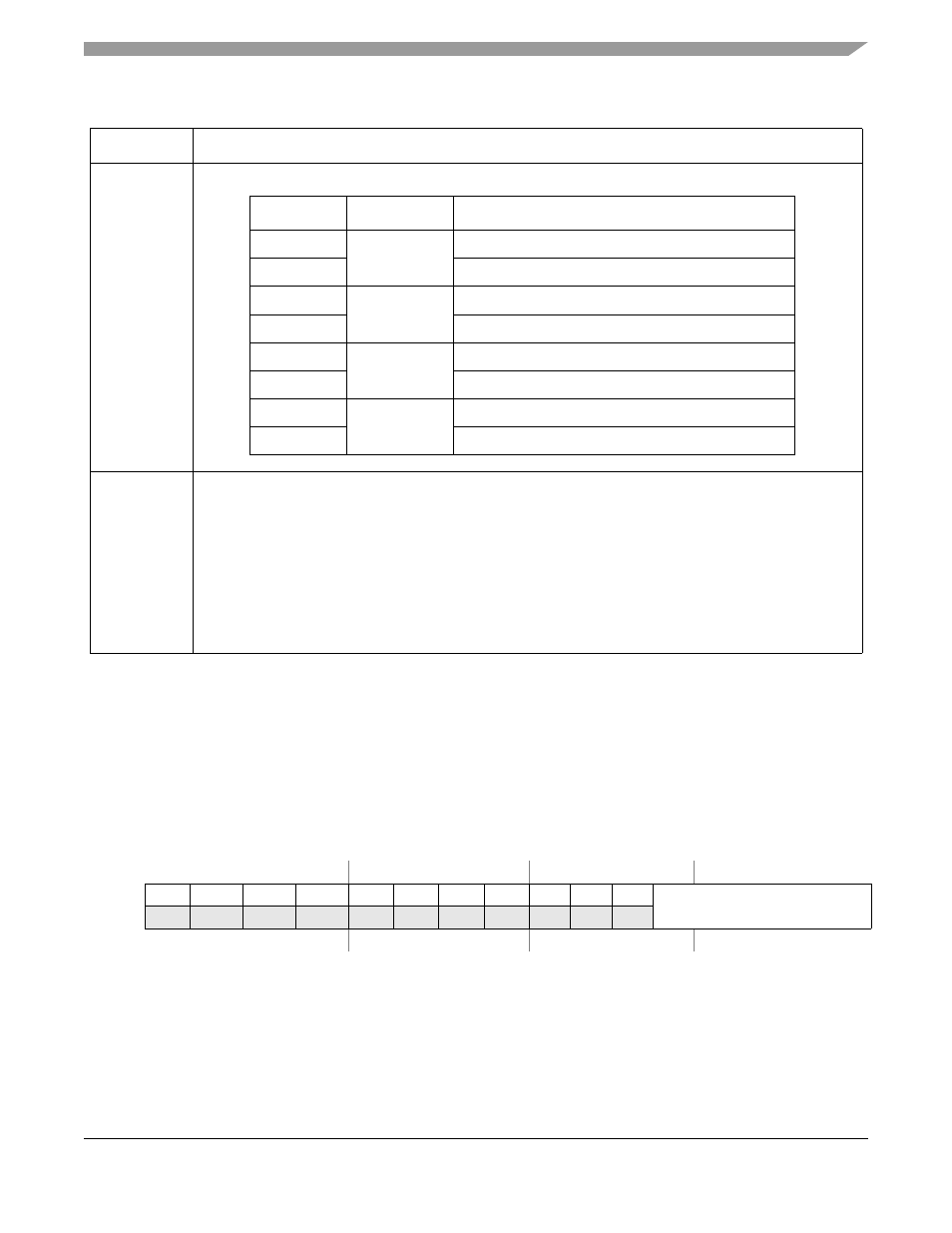
Control 2 Register (CTRL2)
The structure of the CTRL2 register depends on whether the ADC is operating in sequential or parallel
mode (see
Section 26.4.1, “Control 1 Register (CTRL1)
26.4.2.1
CTRL2 Under Sequential Scan Modes
7–4
CHNCFG
Channel Configure. This field configures the inputs for single-ended or differential conversions:
2–0
SMODE
Scan Mode Control. This field controls the scan mode of the ADC module. See
” for details on each scan mode.
000 Once sequential
001 Once parallel
010 Loop sequential
011 Loop parallel
100 Triggered sequential
101 Triggered parallel (default)
110 Reserved; do not use
111 Reserved; do not use
IPSBAR
Offset:
0x19_0002 (CTRL2)
Access: read/write
15
14
13
12
11
10
9
8
7
6
5
4
3
2
1
0
R
0
0
0
0
0
0
0
0
0
0
0
DIV
W
Reset
0
0
0
0
0
0
0
0
0
0
0
0
0
0
1
0
Figure 26-3. Control 2 Register (CTRL2) Under Sequential Scan Modes
Table 26-2. CTRL1 Field Descriptions (continued)
Field
Description
CHNCFG
Inputs
Description
xxx1
AN0–AN1
Configured as differential pair (AN0 is + and AN1 is –)
xxx0
Both configured as single ended inputs
xx1x
AN2–AN3
Configured as differential pair (AN2 is + and AN3 is –)
xx0x
Both configured as single ended inputs
x1xx
AN4–AN5
Configured as differential pair (AN4 is + and AN5 is –)
x0xx
Both configured as single ended inputs
1xxx
AN6–AN7
Configured as differential pair (AN6 is + and AN7 is –)
0xxx
Both configured as single ended inputs