2 memory map, 2 memory map -4 – Freescale Semiconductor ColdFire MCF52210 User Manual
Page 214
Interrupt Controller Module
MCF52211 ColdFire® Integrated Microcontroller Reference Manual, Rev. 2
14-4
Freescale Semiconductor
if interrupt source 8 is active and acknowledged,
then Vector number = 72
if interrupt source 9 is active and acknowledged,
then Vector number = 73
...
if interrupt source 62 is active and acknowledged,
then Vector number = 126
The net effect is a fixed mapping between the bit position within the source to the actual interrupt vector
number.
If there is no active interrupt source for the given level, a special spurious interrupt vector (vector
number = 24) is returned. It is the responsibility of the service routine to manage this error situation.
This protocol implies the interrupting peripheral is not accessed during the acknowledge cycle because the
interrupt controller completely services the acknowledge. This means the interrupt source must be
explicitly disabled in the interrupt service routine. This design provides unique vector capability for all
interrupt requests, regardless of the complexity of the peripheral device.
14.2
Memory Map
The register programming model for the interrupt controllers is memory-mapped to a 256-byte space. In
the following discussion, there are a number of program-visible registers greater than 32 bits. For these
control fields, the physical register is partitioned into two 32-bit values: a register high (the upper
longword, represented by an appended H) and a register low (the lower longword, represented by an
appended L).
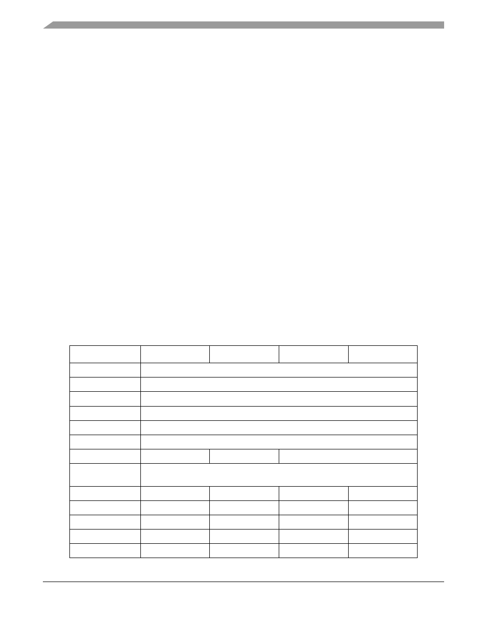
The registers and their locations are defined in
. The register names include the (zero-based)
interrupt controller number n, which is useful in devices with multiple controllers. The MCF52211 has
only one interrupt controller; hence, n = 0.
Table 14-2. Interrupt Controller Memory Map
Module Offset
Bits[31:24]
Bits[23:16]
Bits[15:8]
Bits[7:0]
IPSBAR + 0x0C00
Interrupt Pending Register High (IPRHn), [63:32]
IPSBAR + 0x0C04
Interrupt Pending Register Low (IPRLn), [31:1]
IPSBAR + 0x0C08
Interrupt Mask Register High (IMRHn), [63:32]
IPSBAR + 0x0C0C
Interrupt Mask Register Low (IMRLn), [31:0]
IPSBAR + 0x0C10
Interrupt Force Register High (INTFRCHn), [63:32]
IPSBAR + 0x0C14
Interrupt Force Register Low (INTFRCLn), [31:1]
IPSBAR + 0x0C18
IRLRn[7:1]
IACKLPRn[7:0]
Reserved
IPSBAR + 0x0C1C–
IPSBAR + 0x0C3C
Reserved
IPSBAR + 0x0C40
Reserved
ICRn01
ICRn02
ICRn03
IPSBAR + 0x0C44
ICRn04
ICRn05
ICRn06
ICRn07
IPSBAR + 0x0C48
ICRn08
ICRn09
ICRn10
ICRn11
IPSBAR + 0x0C4C
ICRn12
ICRn13
ICRn14
ICRn15
IPSBAR + 0x0C50
ICRn16
ICRn17
ICRn18
ICRn19