4 buffer descriptor formats, 4 buffer descriptor formats -6 – Freescale Semiconductor ColdFire MCF52210 User Manual
Page 234
Universal Serial Bus, OTG Capable Controller
MCF52211 ColdFire® Integrated Microcontroller Reference Manual, Rev. 2
15-6
Freescale Semiconductor
BDT. The BDT must be located on a 512-byte boundary in system memory. All enabled TX and RX
endpoint BD entries are indexed into the BDT to allow easy access via the USB-FS or ColdFire Core.
When the USB-FS receives a USB token on an enabled endpoint it uses its integrated DMA controller to
interrogate the BDT. The USB-FS must read the corresponding endpoint BD entry and determine if it owns
the BD and corresponding buffer in system memory. To compute the entry point in to the BDT, the
BDT_PAGE registers is concatenated with the current endpoint and the TX and ODD fields to form a
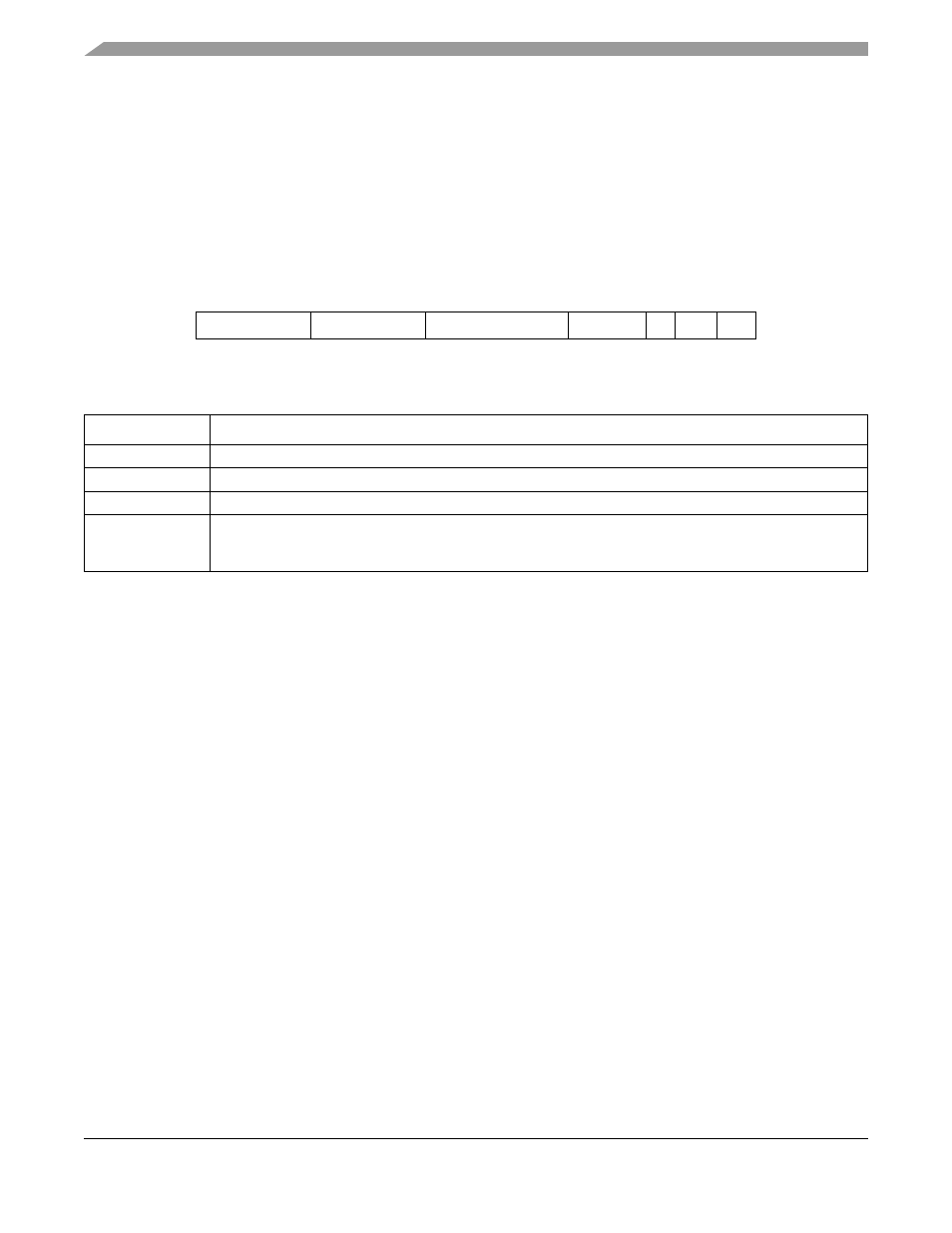
32-bit address. This address mechanism is shown in the following diagrams:
Figure 15-4. BDT Address Calculation
15.3.4
Buffer Descriptor Formats
The Buffer Descriptors (BD) provide endpoint buffer control information for the USB-FS and
microprocessor. The Buffer Descriptors have different meaning based on who is reading the BD in
memory. The USB-FS Controller uses the data stored in the BDs to determine:
•
Who owns the buffer in system memory
•
Data0 or Data1 PID
•
Release Own upon packet completion
•
No address increment (FIFO Mode)
•
Data toggle synchronization enable
•
How much data is to be transmitted or received
•
Where the buffer resides in system memory
While the microprocessor uses the data stored in the BDs to determine:
•
Who owns the buffer in system memory
•
Data0 or Data1 PID
•
The received TOKEN PID
•
How much data was transmitted or received
•
Where the buffer resides in system memory
The format for the BD is shown in the following figure.
31:24 23:16
15:9 8:5
4
3
2:0
BDT_PAGE_03 BDT_PAGE_02 BDT_PAGE_01[7:1] End
Point IN ODD
000
Table 15-2. BDT Address Calculation Fields
Field Description
BDT_PAGE
BDT_PAGE registers in the Control Register Block
END_POINT END
POINT field from the USB TOKEN
TX
1 for an TX transmit transfers and 0 for an RX receive transfers
ODD
This bit is maintained within the USB-FS SIE. It corresponds to the buffer that is currently in use. The buffers
are used in a ping-pong fashion.