FUJITSU PRIMERGY BX600 S3 User Manual
Page 89
BX600 S3
Operating Manual
89
Ethernet I/O Blades
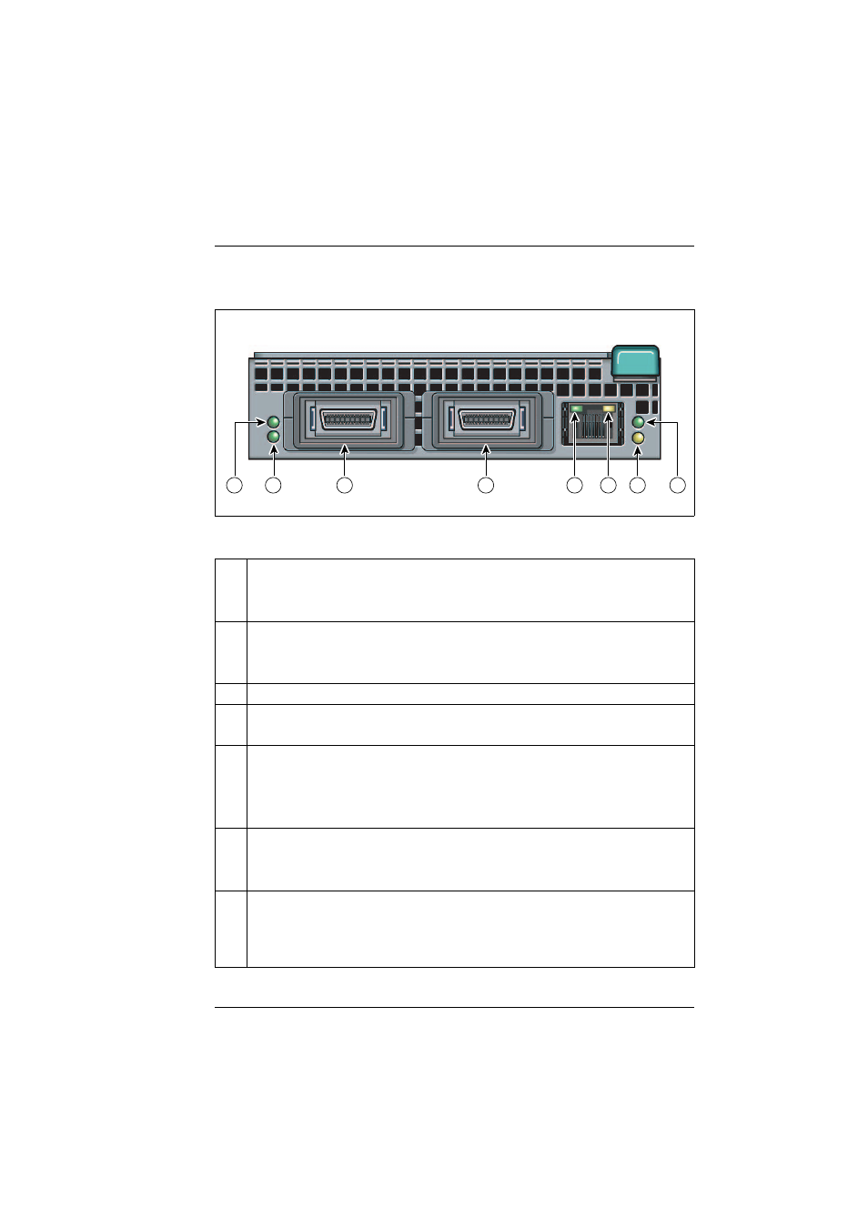
10 Gbit Switch Blade 10/2
Operating and Indicator Elements
Figure 38: 10 Gbit Switch Blade 10/2
1
Left CX4 port indicator (green LED)
Glows:
CX4 link established
Blinks:
CX4 link active
1
Right CX4 port indicator (green LED)
Glows:
CX4 link established
Blinks:
CX4 link active
3,4
CX4 ports
5
Console port link indicator (green LED)
Glows:
Link available
6
Console port active indicator (amber LED)
Dark:
1 Gbit/s link available
Glows:
100 Mbit/s link available
Blinks:
Link active
7
Power indicator (amber LED)
Dark:
Power enabled
Glows:
Power disabled
8
ID indicator (green LED)
Glows:
Switch blade is operating
Blinks:
The switch blade has been selected for identification by the mana-
gement blade.
2
7
8
3
4
5
6
1
See also other documents in the category FUJITSU Computers:
- T2000 (30 pages)
- SPARC ENTERPRISE M3000 (212 pages)
- PRIMERGY RX600 S6 (134 pages)
- BS2000 (37 pages)
- BX900 S1 (144 pages)
- BX900 S1 (142 pages)
- PRIMEQUEST 1000 Series C122-E119EN (109 pages)
- T5120 (26 pages)
- SPARC ENTERPRISE M9000 (560 pages)
- DESKPOWER 2000 (50 pages)
- SPARC M4000 (376 pages)
- ServerView Respurce Orchestrator Virtual Edition V3.1.0 (247 pages)
- PRIMERGY MX130 S2 (256 pages)
- SPARC ENTERPRISE T5120 (58 pages)
- T5240 (28 pages)
- M4000 (310 pages)
- SPARC M4000/M5000 (76 pages)
- TX150 S3 (95 pages)
- SPARC T5220 (240 pages)
- M9000 (518 pages)
- ServerView Resource Orchestrator Cloud Edition V3.1.0 (180 pages)
- PRIMERGY BX600 S2 (173 pages)
- FR family 32-bit microcontroller instruction manuel CM71-00101-5E (314 pages)
- M Server M4000 (30 pages)
- Primergy RX200 S2 (307 pages)
- DESKPOWER P301 (56 pages)
- SPARC Enterprise Server M4000 (62 pages)
- SPARC M8000 (4 pages)
- PRIMERGY B120 (68 pages)
- C120-E361-04EN (36 pages)
- R630 (76 pages)
- 2000 (66 pages)
- T1000 (84 pages)
- Server TX200 S6 (126 pages)
- SPARC ENTERPRISE T5220 (34 pages)
- SPARC M3000 (56 pages)
- TX300 (122 pages)
- PRIMERGY BX600 (288 pages)
- DESKPOWER 6000 (105 pages)
- SPARC Enterprise Server M3000 (8 pages)
- SPARC Enterprise Server M3000 (202 pages)
- T850 (18 pages)
- T5440 (212 pages)
- Service View Resource Orchestrator Cloud Edition V3.0.0 (102 pages)