The fan unit, 1 the fan unit, 140 operating manual – FUJITSU PRIMERGY BX600 S3 User Manual
Page 140: The fan unit ventilation concept, Bx600 s3, Figure 82: the fan unit, Table 2: fan unit indicators
140
Operating Manual
BX600
S3
The Fan Unit
Ventilation Concept
©
c
ogn
it
a
s
.
G
e
s
e
lls
c
h
ft
f
ü
r T
e
c
h
ni
k
-D
o
k
u
m
e
n
ta
ti
on m
b
H
20
09
P
fad
:
H
:\
A
p
ri
l\
P
R
IM
E
R
GY
_R
eb
rand
in
g
\v
o
n W
a
lt
er
\b
x
600
_s
3_
ba\
B
X
6
0
0
S
3
_
e
n
\b
la
d
e
-u
s.
k1
3
13.1
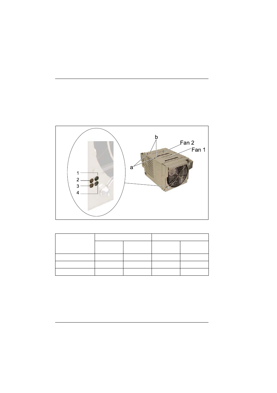
The Fan Unit
The fan unit includes two redundant fans.
There are four LED indicators (
) on the front of the fan unit for fan status
monitoring.
Figure 82: The fan unit
In addition, for each fan in the unit an error LED driven by backup capacitor is
available. These two LEDs (a) are located on the top of the fan unit to indicate
the respective defective fan. The LEDs can be activated via a pushbutton (b)
after the fan unit has been removed from the chassis.
Fan condition
Fan 1 LEDs
Fan 2 LEDs
1
(green)
2
(amber)
4
(green)
3
(amber)
Present and OK
ON
OFF
ON
OFF
Not present
OFF
OFF
OFF
OFF
Present and failed
ON
ON
ON
ON
Table 2: Fan unit indicators
- T2000 (30 pages)
- SPARC ENTERPRISE M3000 (212 pages)
- PRIMERGY RX600 S6 (134 pages)
- BS2000 (37 pages)
- BX900 S1 (144 pages)
- BX900 S1 (142 pages)
- PRIMEQUEST 1000 Series C122-E119EN (109 pages)
- T5120 (26 pages)
- SPARC ENTERPRISE M9000 (560 pages)
- DESKPOWER 2000 (50 pages)
- SPARC M4000 (376 pages)
- ServerView Respurce Orchestrator Virtual Edition V3.1.0 (247 pages)
- PRIMERGY MX130 S2 (256 pages)
- SPARC ENTERPRISE T5120 (58 pages)
- T5240 (28 pages)
- M4000 (310 pages)
- SPARC M4000/M5000 (76 pages)
- TX150 S3 (95 pages)
- SPARC T5220 (240 pages)
- M9000 (518 pages)
- ServerView Resource Orchestrator Cloud Edition V3.1.0 (180 pages)
- PRIMERGY BX600 S2 (173 pages)
- FR family 32-bit microcontroller instruction manuel CM71-00101-5E (314 pages)
- M Server M4000 (30 pages)
- Primergy RX200 S2 (307 pages)
- DESKPOWER P301 (56 pages)
- SPARC Enterprise Server M4000 (62 pages)
- SPARC M8000 (4 pages)
- PRIMERGY B120 (68 pages)
- C120-E361-04EN (36 pages)
- R630 (76 pages)
- 2000 (66 pages)
- T1000 (84 pages)
- Server TX200 S6 (126 pages)
- SPARC ENTERPRISE T5220 (34 pages)
- SPARC M3000 (56 pages)
- TX300 (122 pages)
- PRIMERGY BX600 (288 pages)
- DESKPOWER 6000 (105 pages)
- SPARC Enterprise Server M3000 (8 pages)
- SPARC Enterprise Server M3000 (202 pages)
- T850 (18 pages)
- T5440 (212 pages)
- Service View Resource Orchestrator Cloud Edition V3.0.0 (102 pages)