Control and connection panel, 2 (see also, 1 (see also – FUJITSU PRIMERGY BX600 S3 User Manual
Page 114: 1 control and connection panel, 114 operating manual, Control and connection panel management blade, Bx600 s3
114
Operating Manual
BX600
S3
Control and Connection Panel
Management Blade
©
c
ogn
it
a
s
.
G
e
s
e
lls
c
h
ft
f
ü
r T
e
c
h
ni
k
-D
o
k
u
m
e
n
ta
ti
on m
b
H
20
09
P
fad
:
H
:\
A
p
ri
l\
P
R
IM
E
R
GY
_R
eb
rand
in
g
\v
o
n W
a
lt
er
\b
x
600
_s
3_
ba\
B
X
6
0
0
S
3
_
e
n
\b
la
d
e
-u
s.
k1
0
10.1
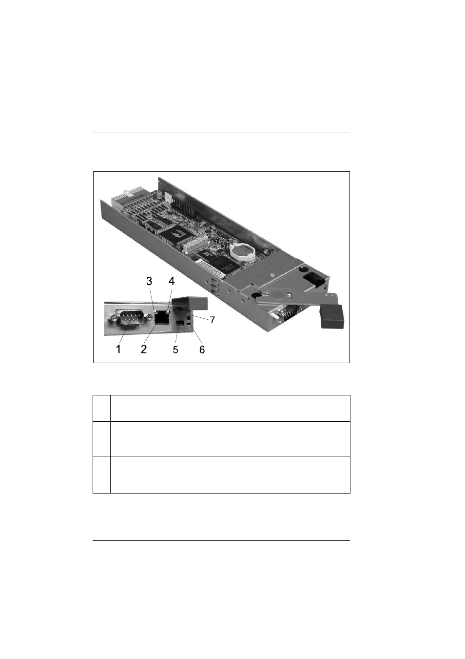
Control and Connection Panel
Figure 61: Management blade control and connection panel
The following indicator and connection elements are provided:
1
Serial port connector
Standard serial port, management communication port.
2
LAN connector (with two integrated LAN status LEDs (see next
positions 3 and 4))
LAN port, RJ45, 10/100 MB management LAN.
3
LAN link indicator (green LED)
Lights green:
The LAN is linked.
Blinks green:
Boot up power ready indicator.
See also other documents in the category FUJITSU Computers:
- T2000 (30 pages)
- SPARC ENTERPRISE M3000 (212 pages)
- PRIMERGY RX600 S6 (134 pages)
- BS2000 (37 pages)
- BX900 S1 (142 pages)
- BX900 S1 (144 pages)
- PRIMEQUEST 1000 Series C122-E119EN (109 pages)
- T5120 (26 pages)
- SPARC ENTERPRISE M9000 (560 pages)
- DESKPOWER 2000 (50 pages)
- SPARC M4000 (376 pages)
- ServerView Respurce Orchestrator Virtual Edition V3.1.0 (247 pages)
- PRIMERGY MX130 S2 (256 pages)
- SPARC ENTERPRISE T5120 (58 pages)
- T5240 (28 pages)
- M4000 (310 pages)
- SPARC M4000/M5000 (76 pages)
- TX150 S3 (95 pages)
- SPARC T5220 (240 pages)
- M9000 (518 pages)
- ServerView Resource Orchestrator Cloud Edition V3.1.0 (180 pages)
- PRIMERGY BX600 S2 (173 pages)
- FR family 32-bit microcontroller instruction manuel CM71-00101-5E (314 pages)
- M Server M4000 (30 pages)
- Primergy RX200 S2 (307 pages)
- DESKPOWER P301 (56 pages)
- SPARC Enterprise Server M4000 (62 pages)
- SPARC M8000 (4 pages)
- PRIMERGY B120 (68 pages)
- C120-E361-04EN (36 pages)
- R630 (76 pages)
- 2000 (66 pages)
- T1000 (84 pages)
- Server TX200 S6 (126 pages)
- SPARC ENTERPRISE T5220 (34 pages)
- SPARC M3000 (56 pages)
- TX300 (122 pages)
- PRIMERGY BX600 (288 pages)
- DESKPOWER 6000 (105 pages)
- SPARC Enterprise Server M3000 (8 pages)
- SPARC Enterprise Server M3000 (202 pages)
- T850 (18 pages)
- T5440 (212 pages)
- Service View Resource Orchestrator Cloud Edition V3.0.0 (102 pages)