Figure 3-12. relief valve, Relief valve, Figure 3-11. exiting and saving calibration – Hale 5.0 FoamLogix User Manual
Page 91: Ιιι -11
ΙΙΙ
-11
ROTARY GEAR PUMP
ELECTRONIC FOAM PROPORTIONING SYSTEM
Section
III
: Set-up and Calibration
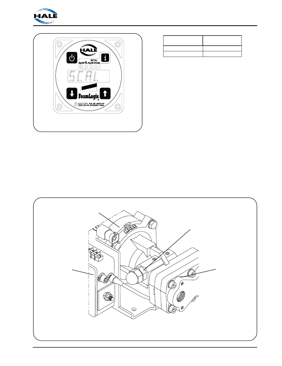
Figure 3-12. Relief Valve
FOAMLOGIX
FOAM PUMP
ASSEMBLY
DISTRIBUTION
BOX
ELECTRIC
MOTOR
PRESET RELIEF
VALVE
RELIEF VALVE
The pressure relief valve (see figure 3-12) is
factory tested and set to values shown in
the following table. During normal
installation and operation the relief valve
will not require adjustment. If adjustment is
necessary in field installation contact Hale
Products Inc for Relief Valve Service bulletin.
Figure 3-11. Exiting and Saving
Calibration
R
E
T
S
A
M
M
A
O
F
E
L
A
H
L
E
D
O
M
T
E
S
E
V
L
A
V
F
E
I
L
E
R
E
R
U
S
S
E
R
P
0
.
5
L
E
D
O
M
)
R
A
B
1
2
(
I
S
P
0
0
3
3
.
3
L
E
D
O
M
)
R
A
B
8
2
(
I
S
P
0
0
4
This manual is related to the following products: