Saddle clamp installation, Ιι -14 – Hale 5.0 FoamLogix User Manual
Page 44
ΙΙ
-14
ROTARY GEAR PUMP
ELECTRONIC FOAM PROPORTIONING SYSTEM
Section
II
: Installation
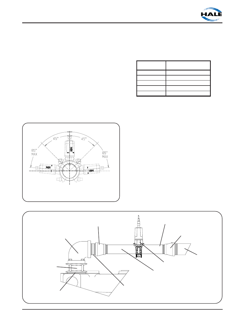
on the flowsensor outlet. In the short length
of reduced pipe pressure loss will be
minimal and there will be minimal pressure
loss through elbows and fittings. Figure 2-9
shows a typical reduced piping run
installation.
Excessive turbulence in the flowsensor may
produce unstable and inaccurate flow
readings. The length of straight pipe prior to
the flowsensor must be sufficient to reduce
the turbulence in the pipe. The following
installation guidelines will help attain the
best readings, and maintain the accuracy
of the Hale FoamLogix system.
a. A minimum 6 times the pipe diameter
of straight run pipe without any fittings is
necessary prior to the flowsensor
paddlewheel (see figure 2-10). Minimum
required straight pipe run:
e
z
i
S
e
p
i
P
d
e
d
n
e
m
m
o
c
e
R
m
u
m
i
n
i
M
e
p
i
P
n
u
R
t
h
g
i
a
r
t
S
)
m
m
8
3
(
.
n
i
½
-
1
)
m
m
1
9
1
(
.
n
i
9
)
m
m
0
5
(
.
n
i
2
)
m
m
4
5
2
(
.
n
i
2
1
)
m
m
4
6
(
.
n
i
½
-
2
)
m
m
7
1
3
(
.
n
i
5
1
)
m
m
6
7
(
.
n
i
3
)
m
m
1
8
3
(
.
n
i
8
1
)
m
m
2
0
1
(
.
n
i
4
)
m
m
8
0
5
(
.
n
i
4
2
b. The downstream piping length is not
as critical but there should be a short
length of straight pipe with no fittings or
valves immediately after the flowsensor
paddlewheel.
c. Do not mount a flowsensor directly
after an elbow or valve. Valves create
severe turbulence when they are
“gated”.
SADDLE CLAMP INSTALLATION
Installation of the Paddlewheel Flowsensor
using a saddle clamp requires a 1.385/1.390
inch bored hole in the pipe. A minimum of
six times the pipe diameter of straight run
pipe without any fittings is necessary prior to
the position of the hole.
Figure 2-9. Typical Reduced Flowsensor Piping Arrangement
Figure 2-8. Flowsensor Tee Position Range
in Horizontal Piping Runs
HALE 2H98 ELBOW
2-½ INCH NPT
OUTLET
2-½ INCH X 2 INCH
NPT REDUCER
2-½ INCH
DIAMETER PIPE
2-½ INCH NPT
CLOSE NIPPLE
2 INCH DIAMETER
PIPE NIPPLE
MINIMUM 10 INCHES LONG
2 INCH DIAMETER PIPE
NIPPLE
2-½ INCH X 2 INCH
NPT REDUCER
HALE 3 INCH
CHECK VALVE
MIDSHIP PUMP
CONNECTION
HALE HPF 20
FLOWSENSOR