Hale 5.0 FoamLogix User Manual
Page 43
ΙΙ
-13
ROTARY GEAR PUMP
ELECTRONIC FOAM PROPORTIONING SYSTEM
Section
II
: Installation
consider the minimum and maximum flow
requirements during operation. Refer to the
flowsensor selection chart in Section
Ι
of this
manual for proper pipe size for flow range
desired.
The flowsensor is installed in the piping
before the foam concentrate injection
point.
Some applications may require flowsensor
accuracy that is not within the range
specified for the discharge piping. This is
true in applications where the foam system
needs to supply a 3 inch deck gun as well
as a 1 inch booster line. Since the flow
through the deck gun will exceed the
capacity of the foam pump, pipe size for
flowsensor mounting should be selected to
provide accuracy at the lower flows.
Mounting the flowsensor in a short section of
pipe one pipe size smaller (4 inch to 3 inch,
3 inch to 2-½ inch, 2-½ inch to 2 inch or 2
inch to 1-½ inch) provides better accuracy
at the lower flows. Refer to the flowsensor
selection chart in Section
Ι
of this manual for
pipe size. Selection of the next smaller pipe
permits reducing the straight pipe run the
required distance prior to the flowsensor
paddlewheel then increasing the pipe size
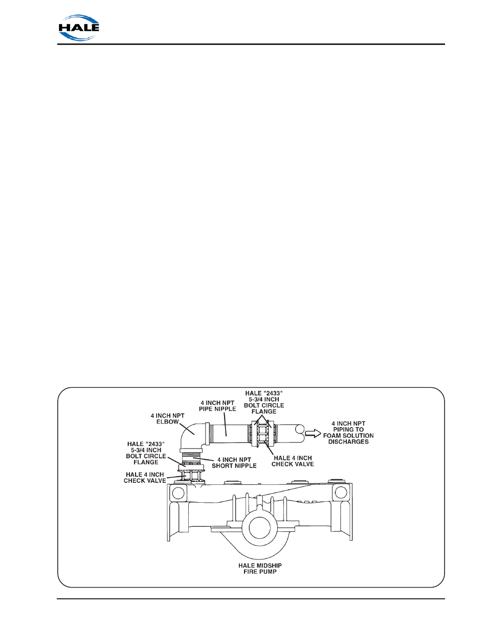
Figure 2-7 shows a suggested installation
arrangement using Hale 4 inch check
valves, Hale 2433 flanges and 4 inch pipe.
WATERWAY CHECK VALVES
Check valves in the waterway, rated at 500
PSI (34 BAR), are required to keep foam
solution out of the main pump and allow
pump priming without drawing foam into
the piping. Using double check valves,
separated by at least 8 inches (203 mm) of
pipe before the foam injection point, helps
ensure that pump and tank water remain
uncontaminated.
FLOWSENSOR
Hale FoamLogix flowsensor is specially
designed to make inspection and
maintenance of the flow sensor easy. The
flowsensor paddlewheel is installed on a
saddle clamp or weld fitting on the foam
capable discharge piping of the
apparatus. In horizontal piping runs, the
flowsensor should be mounted as close to
upright as possible within the range shown
in figure 2-8. DO NOT let the flowsensors
rotate more than 85
o
in either direction for
proper operation.
When selecting flowsensor it is important to
Figure 2-7. Typical 4 Inch Check Valve Installation on Midship Pump