Hale 5.0 FoamLogix User Manual
Page 46
ΙΙ
-16
ROTARY GEAR PUMP
ELECTRONIC FOAM PROPORTIONING SYSTEM
Section
II
: Installation
to making connections.
NOTE: Foam concentrate gravity fed.
FOAM STRAINER
IN-LINE STRAINER/VALVE ASSEMBLY
CAUTION: The in-line strainer/valve
assembly is a low pressure device and
WILL NOT withstand flushing water
pressure. When installing the in-line
strainer in systems equipped with Hale
MDT
ΙΙ
or Hale MST make sure the in-line
strainer/valve assembly is in the hose on
the inlet side of the valve. If the strainer
will be subject to flushing water pressure,
use Hale FS series strainers.
The in-line strainer/valve assembly has 1-1/4
inch NPT female threaded ports. Fittings are
supplied for connection of ¾ inch (19 mm),
1 inch (25 mm) or 1-1/4 inch (32 mm) inside
diameter hose depending on the viscosity
of foam concentrates used. (See figure 2-
12) Generally ¾ inch inside diameter hose
will be used for Class A foam and 1 inch
inside diameter hose will be used for Class B
foams. For high viscosity Class B foam
concentrates it may be necessary to use 1-
1/4 or 1-1/2 inside diameter hose. A
bracket is included with the in-line strainer/
valve assembly to permit installation on the
apparatus.
The hose from the foam tank(s) to the
strainer should have adequate wall stiffness
to withstand the vacuum of the foam pump
while it is operating [23 inches (584 mm) Hg
and 50 PSI (3 BAR)] (Kuriyama, Kuri-tec K-
7130 series or equal).
The following procedures are provided for
installation of the in-line strainer/valve
assembly:
1. Choose a location on the apparatus
that allows gravity feed from the foam
tank to the strainer inlet and from the
strainer outlet to the foam pump suction
connection.
NOTE: When selecting the strainer
location make sure there is sufficient
space below the strainer for removal of
the strainer basket and screen for
cleaning. A minimum of 5 inches (127
mm) is required for this purpose. Also
make sure there is at least 2 inches (51
mm) above the strainer assembly to
permit operation of the service valve.
(Refer to figure 2-12)
2. Refer to the diagram in figure 2-13 and
mark 4 holes for mounting the foam
strainer bracket. The holes must be
drilled to accommodate ¼-20 UNC
screws. The holes can either be tapped
(#7 drill for ¼-20 UNC tap) or drill large
enough to use screws, nuts and washers
(9/32 inch (7 mm) diameter) to secure
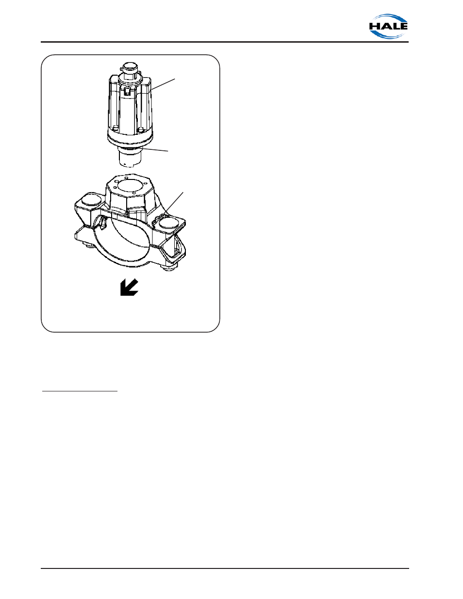
Figure 2-11. Flowsensor Sensor Service
WATER FLOW DIRECTION
SADDLE CLAMP
O-RINGS
SENSOR