Adt air connections, Figure 2-19. bypass valve assembly, Ιι -21 – Hale 5.0 FoamLogix User Manual
Page 51
ΙΙ
-21
ROTARY GEAR PUMP
ELECTRONIC FOAM PROPORTIONING SYSTEM
Section
II
: Installation
foam tank or to assist in priming of the foam
pump. The hose from the BYPASS port must
be long enough to reach a container
outside the truck. This hose must be coiled
for storage when not in use.
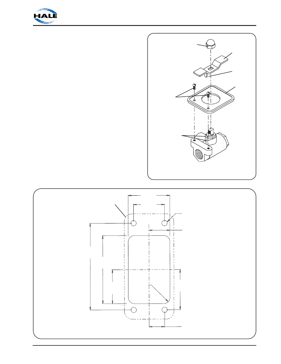
If the handle or placard is removed from
the bypass valve for repairs or to facilitate
remote mounting make sure they are
installed on the valve correctly. Make sure
the tang on the handle engages the cast
stops as shown in figure 2-9.
ADT AIR CONNECTIONS
If the ADT option is used, install the
operating switch and indicator light placard
for the ADT on the apparatus operator
panel. A mounting cutout diagram is
provided as figure 2-20.
After mounting the placard assembly install
the air hoses from the ADT to the placard
assembly. Make sure proper connections
are made at the placard assembly as
Figure 2-19. Bypass Valve Assembly
ACORN NUT
BYPASS HOSE
CONNECTION
INJECT HOSE
CONNECTION
PLACARD
CAST
BOSSES
HANDLE
TANG
PLACARD
SCREWS
HANDLE
Figure 2-20. ADT Panel Placard Panel Cutout and Hole Dimensions
0.84 IN.
(21 mm)
DRILL 4 THRU HOLES
7/32 IN. (6 mm) DIA.
0.63 IN.
(16 mm)
0.25 IN.
(6 mm)
RADIUS
TYP.
3.50 IN.
(89 mm)
2.75 IN.
(70 mm)
1.38 IN.
(35 mm)
1.63 IN.
(41 mm)
1.69 IN.
(43 mm)
1.25 IN.
(32 mm)
PLACARD OUTLINE SHOWN
FOR REFERENCE ONLY