Hale 5.0 FoamLogix User Manual
Page 67
ΙΙ
-37
ROTARY GEAR PUMP
ELECTRONIC FOAM PROPORTIONING SYSTEM
Section
II
: Installation
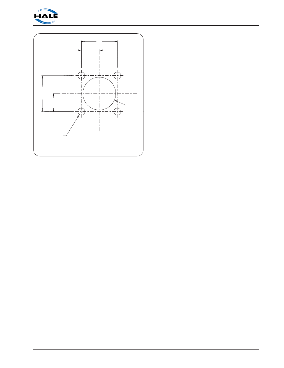
1. Using dimensions in figure 2-27, layout
and drill holes in the top of the foam
tank. The center of the sensor should be
located at least 1-½ to 2 inches (38 to 51
mm) from the sides of the foam tank.
NOTE: The minimum depth of foam tank
for installation of the top mount sensor
without cutting the tube sections is 31-½
inches (800 mm). If the tank depth is less
than 31-½ inches (800 mm) cut the
tubing as described in step c.
2. Determine the approximate length of
the top mount low tank sensor extension
by measuring from the top of the foam
tank at the flange opening to the
bottom of the tank. When properly
installed the center of the sensor float
should be 1-½ to 2 inches (38 to 51 mm)
above the bottom of the foam tank.
3. Slide the flange to the top of the 5/8
inch diameter tube and adjust the
telescoping section until the desired
length is achieved as measured from
the bottom of the flange to the bottom
of the sensor. Tighten the compression
fittings on the union to lock length.
CAUTION: Use mounting hardware that
is compatible with all foam
concentrates to be used in the system.
Use washers, lockwashers and
capscrews made of brass or 300 series
stainless steel.
4. Insert sensor assembly through the
1.31 inch (33 mm) hole and align the
screw holes on the flange and gasket
with the holes on the tank. Secure the
assembly in place using four ¼-20 UNC x
1 inch long cap screws, ¼ inch washers
and ¼ inch lockwashers.
5. Make final adjustment to the sensor
position by pulling the tubing sections up
through the flange until sensor is 1-½ to 2
inches (38 to 51 mm) from the bottom of
the tank. Tighten the 5/8 tube
compression nut on the flange.
6. Close strain relief to the 90
0
position
making sure it snaps shut. Tighten strain
relief gland nut to seal out water and
contamination.
RESIZING THE LOW LEVEL SENSOR
Some applications may require the top
mounted sensor to be shorter than
factory length. Use the following
procedure only if the tube sections are
too long otherwise proceed to step d.
Refer to figure 2-28, disassemble and cut
the tube sections as follows:
1) Loosen and remove the
3
/
8
FNPT x
5
/
8
tube fitting and strain relief from the top
of the sensor assembly. Carefully slide
the sensor wire out of the strain relief
gland.
2) Loosen and remove the ¼ FNPT x ½
tube fitting and sensor from the bottom
of the sensor assembly. DO NOT remove
the ½ inch tube from the
5
/
8
inch tube.
Figure 2-27. Top Mount Low Tank Switch
Mounting Flange Cutout Dimensions
1.44 in.
(37 mm)
0.72 in.
(18 mm)
(4) Thru Holes
0.281 in. (7 mm)
1.31 in.
(33 mm)
Dia. Thru
Hole
0.72 in.
(18 mm)
1.44 in.
(37 mm)